Festo Controller CECC
12
3.5 Interfaces
3.5.1 I/O interface X2-X5
The I/O interface of the CECC enables sensors (inductive, capacitive, etc.) or signal generators (counters)
to be evaluated and signal receivers to be actuated. All digital inputs and outputs as well as their power
supply are connected to the CECC via the contact strip.
The I/O interface of the CECC has:
– 12 digital inputs (PNP, 24 V DC, typ. 3 ms input delay)
– 2 fast digital inputs (for fast counters)
– 8 digital outputs (positive switching, 24 V DC, 0.5 A/module, total current 4 A)
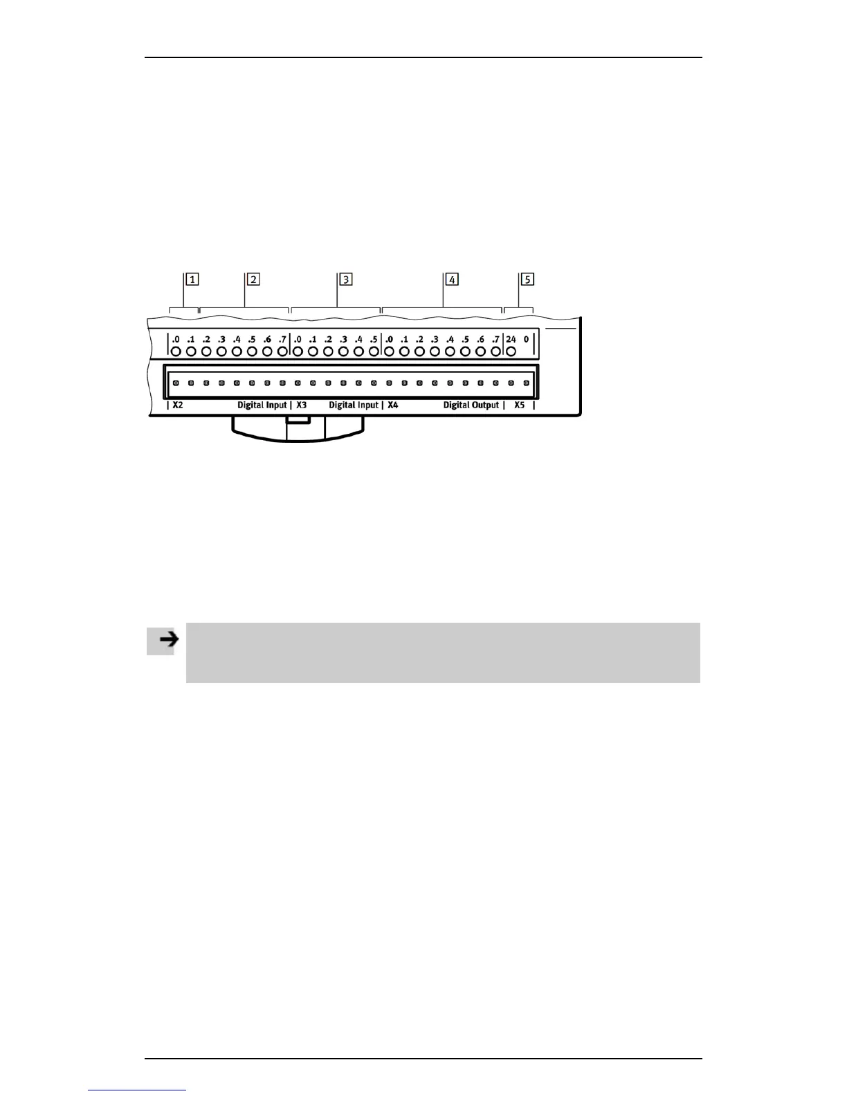
1
Fast inputs X2.0 and X2.1
2
Inputs X2.2 to X2.7 (1 kHz)
3
Inputs X3.0 to X3.5 (1 kHz)
4
Outputs X4.0 to X4.7
5
Power supply for I/O interface X5 (24 V)
Figure: I/O interface of the CECC
Connecting the I/O interface
Note
Using the wrong connections can damage the device.
• Use connection 5 for the power supply to the E/A interfaces.
• Connect the digital inputs and outputs to sensors and actuators.
Appropriate contact strips can be found at www.festo.com/catalogue.
Further information on using the I/O interface can be found in the online Help for the
Festo CECC_3 library.