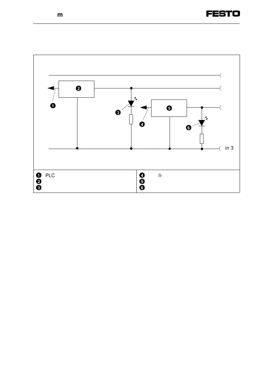
Internal layout of CP-E16-M12x2 (PNP inputs)
1
2
3
PLC/I-PC Ex+1 (e.g. via field bus)
Logic recognition Ex+1
Green LED Ex+1
4
5
6
PLC/I-PC Ex (e.g. via field bus)
Logic recognition Ex
Green LED Ex
Fig. 1/8: Internal layout of input module CP-E16-M12x2
24 V +10/-15%
Pin 1
Pin 2
5
3
2
6
Pin 4
Pin 3
4
1
0V
1. Input module type CP-E16...-M...
CP-E16...-M... 9611A 1-13