1. Installation
1−29
Festo P. BE−CPX−FB11−E N en 0503b
System supply,
additional power supply
and valve supply
The CPX terminal is supplied with operating and load volt
ages via the manifold bases with s
ystem supply, additional
supply and valve supply types CPX−GE−EV−S..., CPX−GE−EV−Z...
or CPX−GE−EV−V...
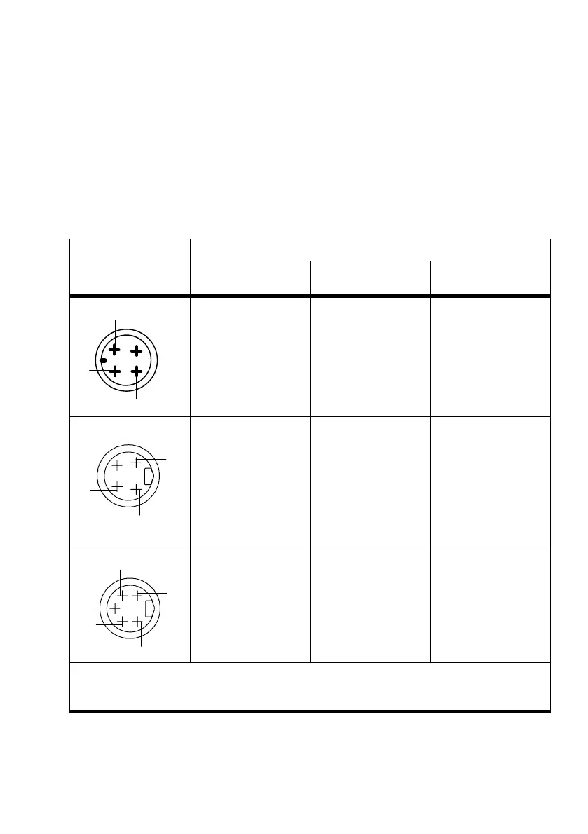
Plug
Pin assignment of manifold base with
System supply
type CPX−GE−EV−S...
Additional supply
type CPX−GE−EV−Z...
Valve supply
type CPX−GE−EV−V...
2
3
4
1
M18
1: 24 V
EL/SEN
2: 24 V
VAL
/ 24 V
OUT
3: 0 V
EL/SEN
/
0 V
VAL
/ 0 V
OUT
4: Earth terminal
1: not connected
2: 24 V
OUT
3: 0 V
OUT
4: Earth terminal
1: not connected
2: 24 V
VAL
3: 0 V
VAL
4: Earth terminal
7/8"−4PIN
D
C
B
A
A:24 V
EL/SEN
B:24 V
VAL
/ 24 V
OUT
C: Earth terminal
D:0 V
EL/SEN
/
0 V
VAL
/ 0 V
OUT
(leading)
Pin designation
Pay attention to the in
formation on the plug.
A: not connected
B:24 V
OUT
C: Earth terminal
D:0 V
OUT
(leading)
Pin designation
Pay attention to the in
formation on the plug.
A: not connected
B:24 V
VAL
C: Earth terminal
D:0 V
VAL
(leading)
Pin designation
Pay attention to the in
formation on the plug.
7/8"−5PIN
1
2
3
4
5
1: 0 V
VAL
/ 0 V
OUT
2: 0 V
EL/SEN
3: Earth terminal
(leading)
4:24 V
EL/SEN
5: 24 V
VAL
/ 24 V
OUT
1: 0 V
OUT
2: not connected
3: Earth terminal
(leading)
4: not connected
5: 24 V
OUT
V
EL/SEN
:Operating voltage for electronics/sensors
V
OUT
: Load voltage outputs
V
VAL
: Load voltage valves
Tab.1/14:Pin assignment for system supply, additional supply and valve supply
 Loading...


