© Festo Didactic 746310 43
13 Terminal assignments, EduKit PA Advanced
Terminal Device Abbreviation Note
I0 Flow sensor, switching output -BF2_GW limit value, adjustable at sensor display
I1 Float switch LA+ -SG11 Optional
I2 Float switch LS- -SG12 Optional
I3 Capacitive proximity sensor -BG13 Minimum level, upper tank
I4 Capacitive proximity sensor -BG14 Maximum level, lower tank
I5 Sensor box BG15 with indicator -BG15_cl Optional, 2-way ball valve V107, closed
I6 Sensor box BG15 with indicator -BG15_op Optional, 2-way ball valve V107, open
Q0 Load relay -KF2 activates-MB2 2/2-way solenoid valve V102
Q2 Change-over relay -K1 Relay = 0: pump is binary controlled
Relay = 1: pump is analogue controlled with 0 to 10 V
Q3 Motor, pump P101 -MA1 ON/OFF, supply with motor controller
Q5 5/2W solenoid valve, spring-returned -MB7 activates rotary drive MM7 for 2A-way ball valve V107
Digital inputs and outputs, I/O terminal (1)
Terminal Device Abbreviation Note
8 Ultrasonic sensor -BL1 Analogue input 0-10 V DC, level height 0…220 mm (0-2,7l)
7 Flow sensor -BF2 Analogue input 0-10 V DC, flow rate 0…10 l/min
15 Pressure sensor -BP3 Analogue input 0-10 V DC, pressure 0…400 mbar
1 Pump -P101 Analogue output 0-10 V DC, manipulated value 0…100%
Analogue inputs and outputs, analogue terminal (2)
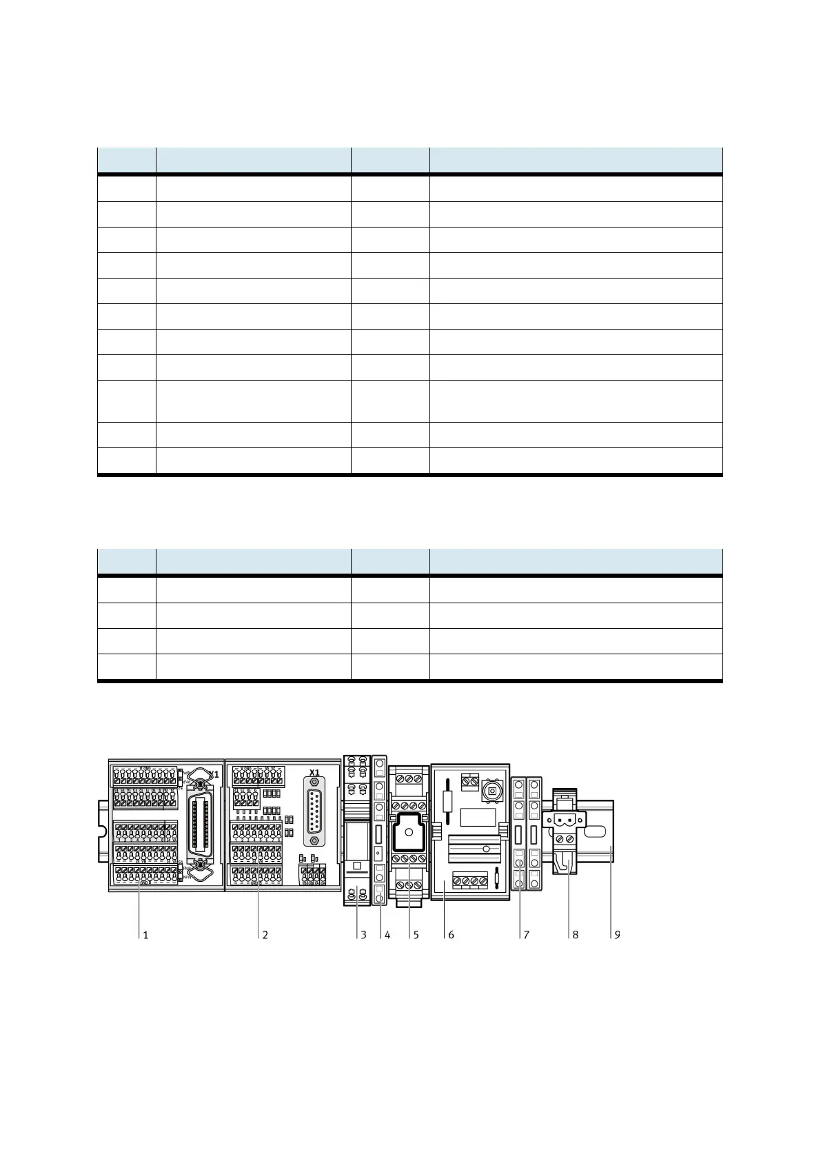
1: I/O terminal XD1; 2: analogue terminal XD3; 3: relay, 2 switch-over contacts KF1; 4: relay, 1 switch-over contact KF2;
5: motor controller QA1; 6: starting current limiter QA0; 7: PE terminals XE0; 8: motor terminal XD20; 9: top hat rail
Complete assignment plan