3. Installation
3−9
Festo P.BE−MTR−DCI−IO−EN en 0606b
3.3 Serial interface
Serial interface for parametrizing, commissioning and
diagnosing
Please note
In order to connect a PC to the MTR−DCI, use exclusively
the following cable from the Festo accessories:
programming cable KDI−MC−M8−SUB−9−...
cable length 2.5 m (maximum permitted signal cable
length).
· If necessary, remove the protective cap from the serial
interface of the MTR−DCI.
· Connect the following connections with the programming
cable:
the connection socket on the MTR−DCI
a serial interface COMx of the diagnostic PC.
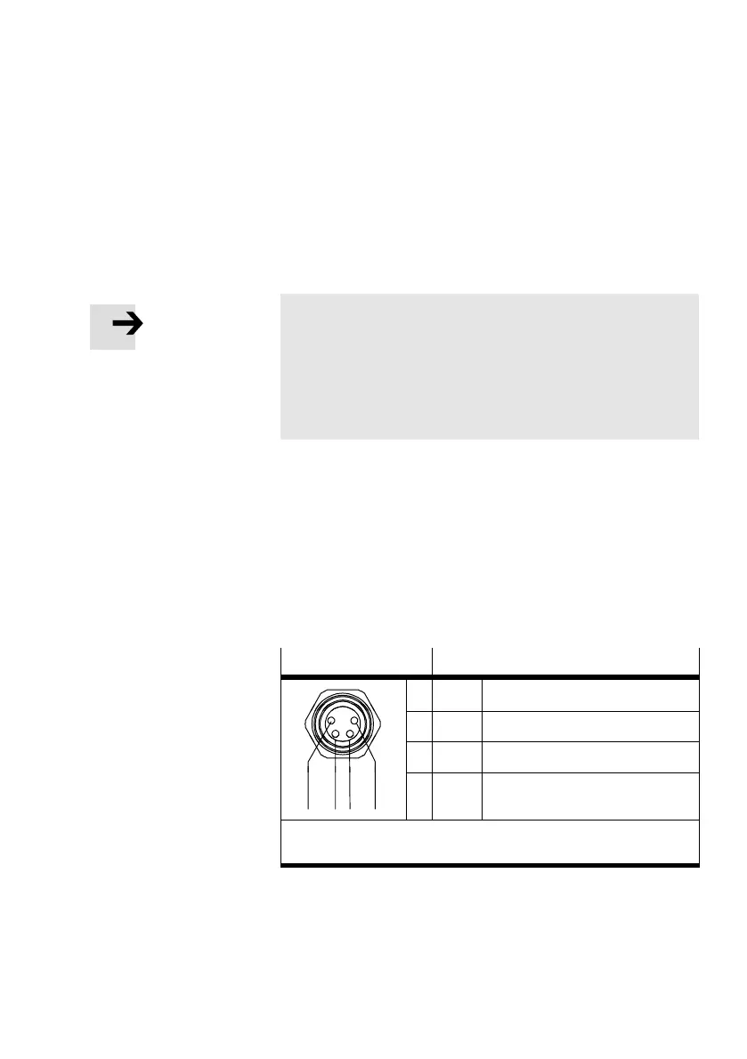
M8x1 socket
Description
1 GND Ground
2 TXD RS232 transmitting cable
1)
3 RXD RS232 receiving cable
1)
1243
4 −−− Reserved for service personal.
Do not connect.
1)
The levels correspond to the RS232 standard and enable a data
transmission rate of 9600 Baud
Tab.3/6: Connecting the serial interface on the MTR−DCI
 Loading...