3. Installation
3−11
Festo P.BE−MTR−DCI−IO−EN en 0606b
3.4 Input for external reference switch
If you are not using a reference switch:
· Seal the connection with the protective cap supplied
(typeISK−M8).
Connecting the reference switch:
· Use the correct switch type normally−open contact" in
the PNP variant for the reference switch.
· Use a sensor with screw locking (external thread M8x1) at
the end of the cable for connecting the reference switch or
use the extension cable type KM8−M8−... with screw lock
ing as adapter for connecting the reference switch.
Use e.g. the following proximity switches from Festo:
electric proximity switch type SMT−8F−...
inductive proximity switch
type SIEN−...−M8B−...
· When selecting the sensor, note that the accuracy of the
switchover point of the sensor determines the accuracy of
the reference point.
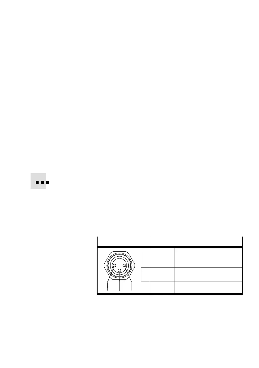
M8x1 socket
Description
1 +24 V DC +24 V DC voltage output
(only for reference switch)
4 REF Contact reference switch
124
3 GND Ground
Tab.3/7: Connection Ref" (reference switch) on the
MTR−DCI
The power supply for the reference switch (24 V DC / Ground)
is provided via pin 1/3.


 To Next Page