20
Wiring
The Primary J1939 communication wires are brought out of the PowerWizard as part of the 70-pin AMP connector. The pins, as
designated on the AMP connector, are shown in Table 2.
Pin # Name Description
34 CAN1 - Dierential (-) for CAN
42 CAN1 SH Shield for CAN
50 CAN1 + Dierential (+) for CAN
Table 2: Primary J1939 Data Link on 70-pin Connector
Network Topology
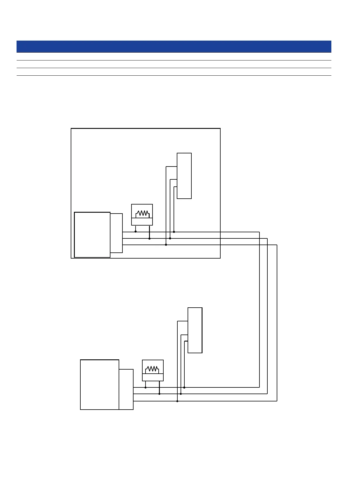
The physical topology of the CAN network used in the Primary J1939 Data Link is a bus topology, consisting of a main trunk and
small drops. The maximum allowable trunk length is 130 ft (40 m) and the maximum drop length is 3 ft (1 m). The CAN network
requires a termination resistor on the extreme ends of the main trunk. The topology for the PowerWizard 1.1 and 1.1+ is illustrated
in Figure 11.
PowerWizard
1.1/1.1+
CANI +
CANI -
CANI SH
50
34
42
J20
Engine ECM
CANI +
CANI -
CANI SH
50
34
42
J1
A B
A B
Terminating
Resistor #1A
Terminating
Resistor #1B
C
F
G
C
F
G
CAN SH
CAN -
CAN +
CAN SH
CAN -
CAN +
Engine Service
Connector
On Electronic Engine
Primary Gen Service
Tool
120 Ohms
120 Ohms
Figure 16: PowerWizard 1.1, 1.1+ CAN Wiring Diagram



 To Next Page