19
13
11
9
Phase A
Phase C
Phase B
POWERWIZARD
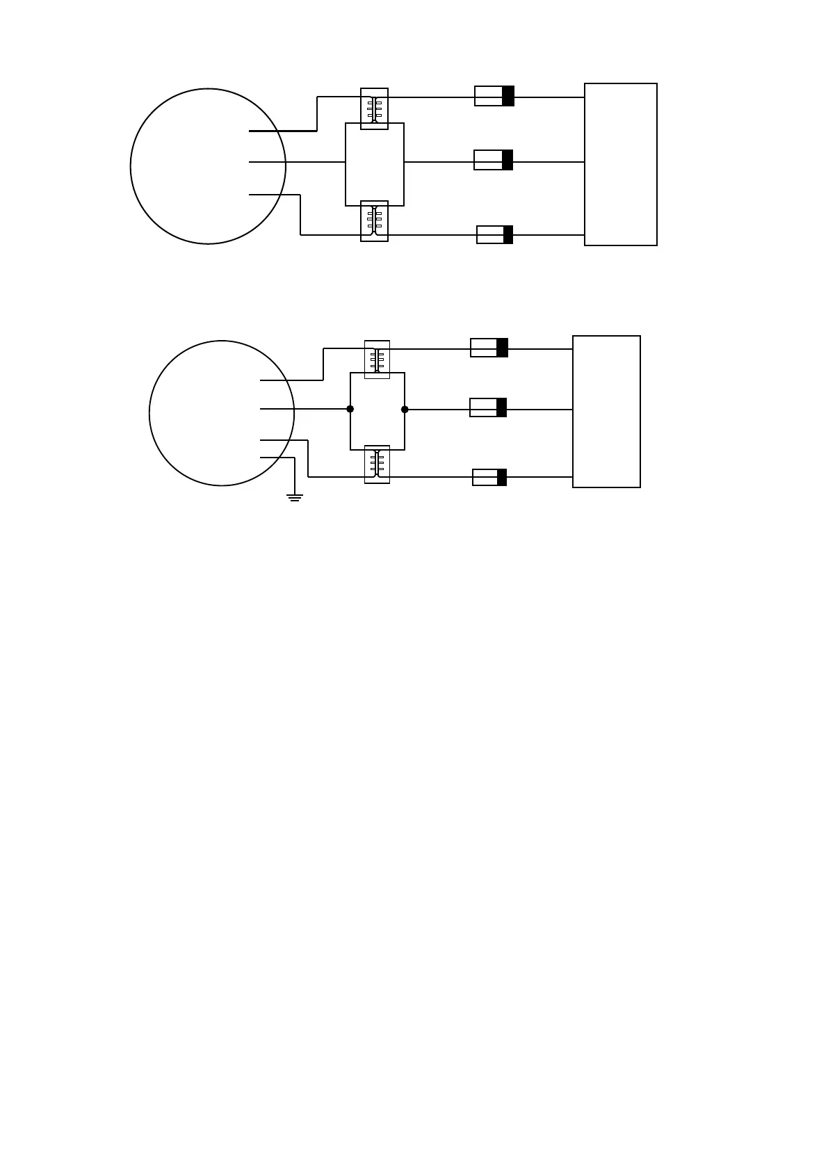
Figure 14: Open Delta Conguration of External Potential Transformers (PT) on the 3-wire Delta connected
Generating Set
13
11
9
Phase A
Phase C
Phase B
POWERWIZARD
Neutral
Figure 15: Open Delta Conguration Of External Potential Transformers (PT) on the 4-wire Wye connected
Generating set
4.6 Data Links
The PowerWizard supports up to 3 dierent data links:
One Primary J1939 Data Link•
One Accessory J1939 Data Link (PowerWizard 2.1 only)•
One System Control and Data Acquisition (SCADA) Data Link (PowerWizard 2.1 only).•
For information on the SCADA system refer to the following manuals:
PowerWizard Monitoring Software (available with MCM7 and MCM8 options)•
PowerWizard Modbus Applications Guide (provided by the aftersales help desk, refer to the contacts list at the back of this •
manual.
4.6.1 Primary J1939 Data Link (CAN1)
The Primary J1939 Data Link is supported by all of the PowerWizard controls.
The Primary J1939 Data Link is used for local communication among modules associated with a single generating set. The
PowerWizard can interface with both Electronic Engines (EUI) and Mechanical Engines (MUI). In MUI engines, the engine
sensors are wired directly to the PowerWizard. The Primary J1939 Data Link utilizes the Society of Automotive Engineers (SAE)
J1939 protocol and requires hardware compliant to the high-speed Controller Area Network (CAN) 2.0B protocol dened in the
International Standards Organization (ISO) 11898-2 document, running at 250k bits per second.
The Primary J1939 Data Link supports appropriate SAE J1939 Broadcast Parameter Group Numbers (PGN) and Suspect Parameter
Numbers (SPN) for engine and generating set data and diagnostics.



 To Next Page