3 Application Interfaces
29
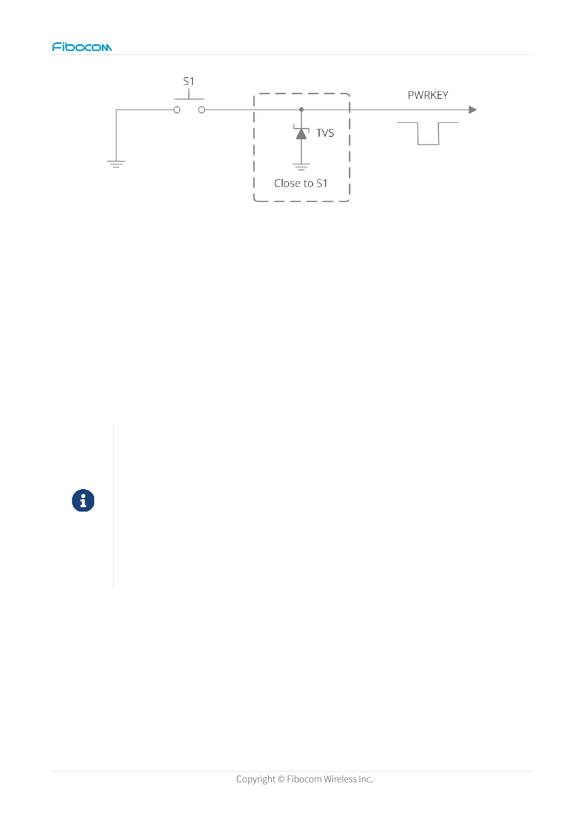
Figure 7. Button control reference circuit
Automatic power-on design: If the module needs to be powered on automatically, the
PWRKEY pin can be connected in series with the resistor to ground (recommended
resistance value is 1KΩ or 0Ω). In this way, the module sleep current will increase by about
0.2mA, and the module can only be directly powered off when it is powered down.
In addition, if you use the automatic power-on design, ensure that the battery/power supply
voltage is not lower than the module automatic power-off voltage, otherwise you need to re-
power up and down again or plug and remove the USB to power on normally.
Before pulling down the PWRKEY pin, make sure that the VBAT voltage is
stable. It is recommended to control the interval from power-up by VBAT to
PWRKEY pin pull-down no less than 30ms.
It is not recommended to design pull-down resistor larger than 1K for automatic
power-on, otherwise it cannot guarantee that PWRKEY voltage is within the
range of effective low level, which will lead to probability failure of boot.
3.2.2 Power-off
Background
The module can be powered off through the following ways:
⚫ Low voltage power-off: The module is powered off when the power supply voltage is lower
than the rated minimum operating voltage. The module does not log out from a base station.
 Loading...