4 RF Interface
54
4.2 RF Antenna
4.2.1 Antenna Introduction
Antenna interface
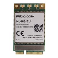
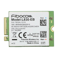
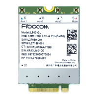
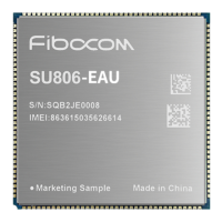
The module only has RF antenna pad. The RF cable can be connected to the antenna after
PCB design of the RF signal line.
Antenna classification
According to the transmitting and receiving functions, it mainly includes:
⚫ Main antenna: The antenna is divided into built-in and external antenna, which is
responsible for RF signal transmission and reception.
The antenna is a sensitive device and is easily affected by the external environment. For
example, the position of the antenna, the occupied space, and the surrounding grounding
may affect the performance of the antenna. In addition, the RF cable connected to the
antenna and the fixed antenna position will also affect the antenna performance.
A shield or module antenna is placed away from the DCDC device on the customer
mainboard to prevent RF signals from interfering with the DCDC device, resulting in out-of-
specification ripple output.
4.2.2 Impedance Design Principles
For modules that do not have a RF connector, you need to route a RF cable to connect to the
antenna feeding point or connector. It is recommended to use a microstrip line. The shorter
the better. The insertion loss should be controlled less than 0.2 dB, and impedance should
be controlled within 50Ω.
In general, the impedance of the RF signal route is determined by the dielectric constant of
the material, the route width (W), the ground clearance (S) and the height of the reference
ground plane (H). The control of the characteristic impedance of the PCB usually is



 To Next Page