4 RF Interface
57
the signal pin should be kept at a certain distance from the ground.
⚫ The reference ground plane of the RF signal cable should be kept intact; adding a certain
amount of ground holes around the signal and the reference ground can improve the RF
performance; the distance between the ground hole and the signal cable should be at least
2 times the cable width (2*W).
⚫ The equivalent capacitance of the TVS should be less than 0.5 pF.
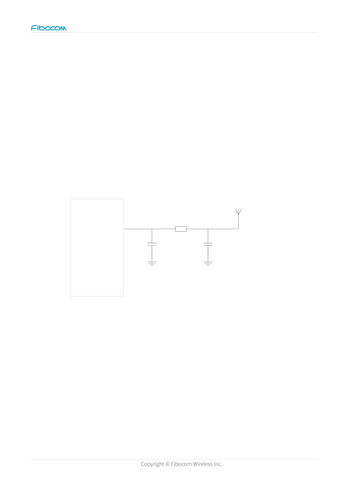
Add a π-type circuit (two parallel component grounding pins are connected directly to the
main GND) between the module and antenna connector (or feeding point) for antenna
debugging. Two parallel components are directly connected across the RF cable, and the
branch must not be pulled out.
Figure 25. Antenna interface peripheral circuit
4.2.3 Antenna Passive Test
You will need: network analyzer and anechoic chamber.
The passive test evaluates the radiation performance of the device by focusing on the
radiation parameters like gain, efficiency and antenna pattern. Although the test considers
the environment (such as the device around the antenna, open and close lid) impact on the
antenna performance, it cannot tell the final radiated transmitting power and receiving
 Loading...