3 Application Interfaces
38
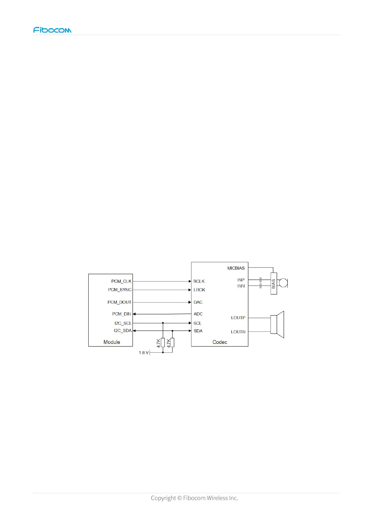
The module digital voice interface supports I2S and PCM transmission standards.
Schematic Diagram Design
According to the corresponding connection of the reference design of the codec chip used,
the power supply and IO level are required to meet the requirements of the codec chip and
match the module.
When the customer uses the external codec and audio power amplifier of the module
interface, it is recommended that the control signal such as the enable of the audio power
amplifier or I2C is also connected to the module to facilitate the debugging of the timing
sequence and solve the audio problems such as pop sound.
It is recommended to use an independent power supply for chip power supply or ensure that
the power supply is clean and noiseless.
RC (0Ω/33pF) filtering is recommended for I2S signals.
Figure 16. Schematic diagram of LCD reference circuit
PCB Design
The audio is partially protected or divided to ensure that the grounding is clean. Keep away
from other interference sources.
Audio signal design requires filtering isolation and packet protection.
I2S_MCLK signal has a high speed, so it must be isolated from other high-frequency or