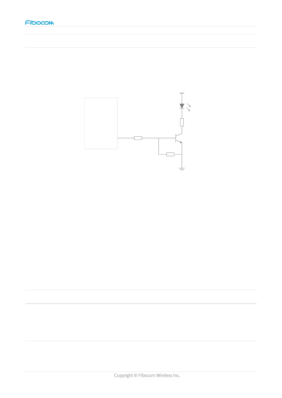
Figure 19. Network status indicator reference circuit
Please reserve the 4.7K and 47K positions for voltage division to ensure that the voltage of
the triode V
BE
is less than the starting voltage of the triode in startup, reset and wake up
scenarios, and avoid power consumption increase caused by LED work. When the LED is
required to work, the voltage of the V
BE
is greater than the starting voltage of the triode.
STATUS indicates the operational status of the module. STATUS will output a high level
when the module is powered on normally. The definition of the STATUS pin is described in
the following table:
Table 29. STATUS operating status
 Loading...