QuickServer Start-up Guide Page 28 of 43
FieldServer Technologies 1991 Tarob Court Milpitas, California 95035 USA Web: www.fieldserver.com
Tel: (408) 262 2299 Fax: (408) 262 2269 Toll Free: (888) 509 1970 email: support@fieldserver.com
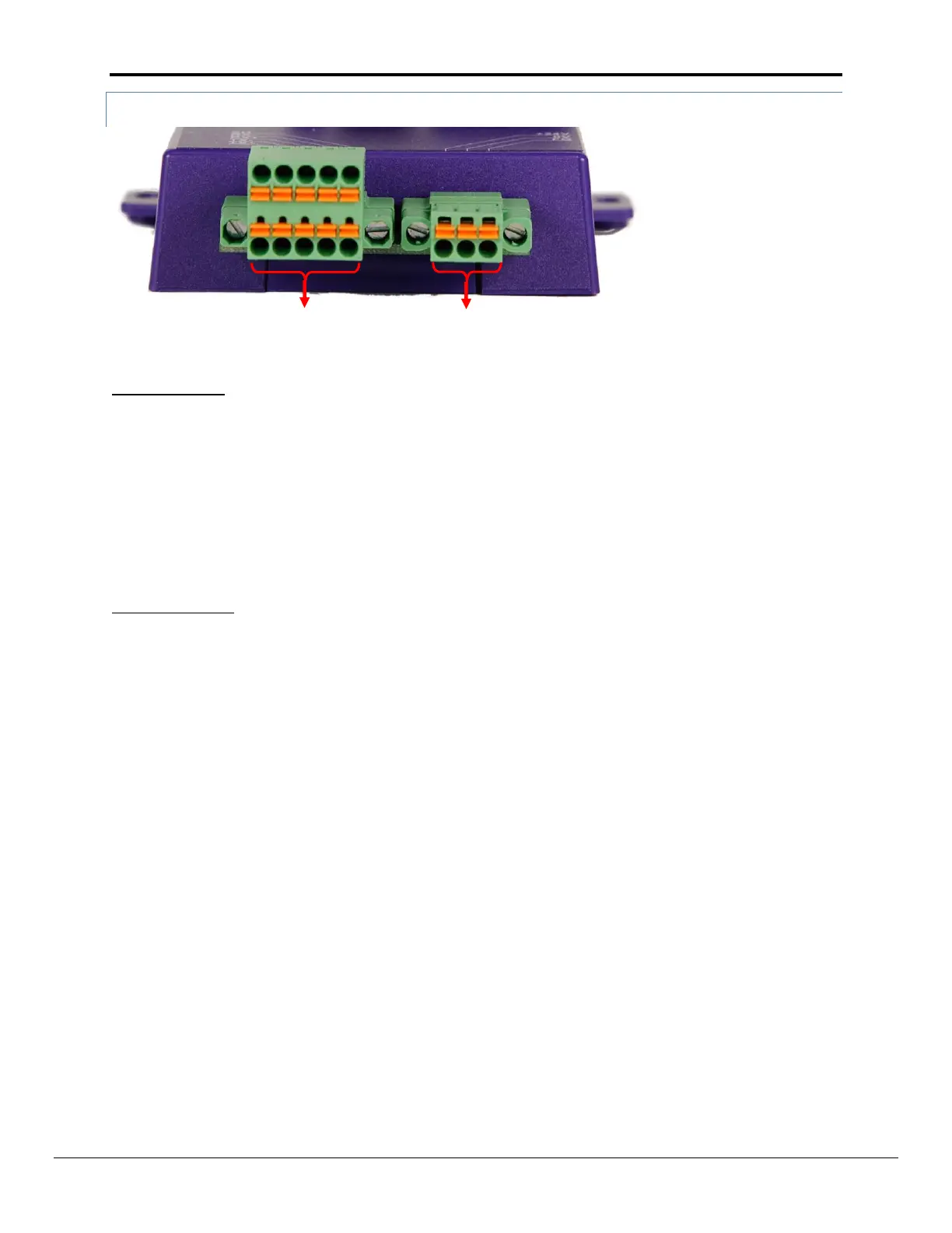
Appendix A.2.1. Connection and Operation of the RS-422 QuickServer
RS422 connector:
Pin 1-2: TX +/- (Differential TX outputs: All + signals must be connected to each other, and same applies to - signals;
no +/- signals may be crossed)
Pin 3-4: RX +/- (Differential RX inputs: All + signals must be connected to each other, and same applies to - signals,
no +/- signals may be crossed)
Pin 5: SHD (Shield connection, must be connected on at least one side of the bus, but not necessarily on both
sides)
POWER connector:
Please note that AC voltage is not supported on the RS-422 Carrier, and that DC voltage range is ~20VDC to
~28VDC.
Pin 1: +24V (DC power requires this pin be used for the positive voltage)
Pin 2: 0V (DC power requires this pin is used for ground / return voltage)
Pin 3: FG (This pin needs to be connected to EARTH or noise free reference point i.e. CHASSIS)