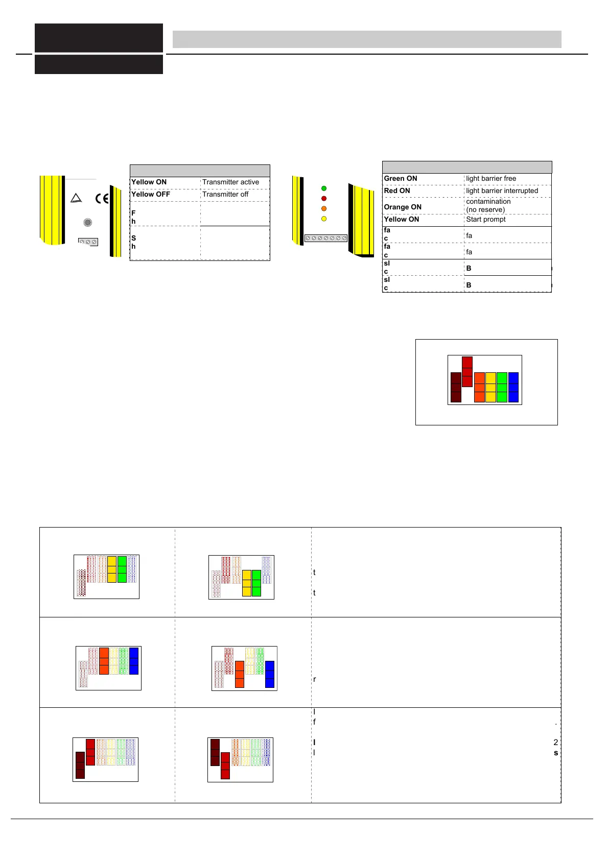
3.5 LED-displays (also refer to chap. 6.2 and 6.3 Commissioning and Trouble-Shooting)
Several LEDs on the receiver indicate the current operating status (Fig. 10/1). If the system test detects an internal or external
fault, the machine will be switched off immediately and the LEDs on the receiver and/or transmitter (if the fault lies within the
transmittter) indicate the fault status to the user by quick flashing.
When a fault is present, the flashing LEDs together with a fault code provide visual output of the detected fault and display in the
diagnostics device.
3.6 Operating mode switches
The DIP switches in the connector cover enable the following operating modes to be selected:
- Safety mode with / without restart interlock
- With / without contactor check
- equivalent / antivalent outputs (Fig. 9/1)
In the condition when delivered, the preset operating mode comprises safety mode with:
restart interlock,
contactor check and
equivalent outputs.
Caution!
The operating mode may only be selected when no voltage is present. If the DIP
switches are actuated during operation, the light barrier will switch off the outputs and
go to locking status. This is indicated by flashing of the yellow and orange LEDs. Locking status will only be ended
once the power supply has been switched off.
The switchgears ULSG, LSUW NSR 3-1-K and LSUW N1-Muting K are available for additional functions such as potential-free
output contacts or muting (Refer to Section 8 for further information and electric connection).
without contactor control
The operating mode with contactor control serves to monitor the
driven succeeding contactors.
After each interruption of the light path and before each release of
the switching outputs, it is checked whether the succeeding
contactors have fallen. Only then will a new release be possible. If
the contactors do not respond within 300 ms, the light barrier
switches off the outputs and goes into locking status.
without restart interlock
With the operating mode with restart interlock selected, a button
must be connected to the start button input for a start release of the
operating movement.
When the protective field is free, the yellow LED lights up on the
receiver as a start prompt. Only once the start button has been
pressed will the outputs of the ULVT/BLVT be switched to active.
In the equivalent outputs operating mode, both PNP outputs are
failsafe and monitored internally for short-circuits and cross-circuits.
With a free light path, both outputs are high (+24 V). In the antiva-
lent outputs operating mode, output 1 is high (+24 V) and output 2
low (0 V) when the light path is free. Output 2 is not failsafe in this
operating mode. This operating mode is only permissible in
conjunction with the safety switchgears LSUW NSR 3-1K,
LSUW N1-Muting K, or another safe sequential phase control
device which monitors output 2!
3 System description - LED-displays/operation modes
Bild 10/2 The operating modes can be set
using the DIP switches. The
condition when delivered is
shown here.
Table 10/3 programming of operation modes
Bild 10/1 LED indicate the operating and/or fault status
Green ON light barrier free
Red ON
Orange ON
light barrier interrupted
contamination
(no reserve)
fast orange flashing
ca. 4 x /s
fast yellow flashing
ca. 4 x /s
slow orange flashing
ca. 1 x /s
BLVT only:: reduced resolution
slow yellow flashing
ca. 1 x /s
BLVT only:: reduced resolution
ULVTE Empfänger
Made in Germany
D-73734 Esslingen, Kastellstr.9
0711/91 96 97 -0
1234567
3:OSSD2
6: 0V
5:
2: EDM
7: 24VDC
±20%
4: OSSD1
1: Start
ULVT Receiver/Récepteur
interdiction de
redémarrage
restart
interlock
adjustment
LC i nterrupt
LC f ree
Aid e
d´àj ustement
libre
interrompu
BWS Typ4 , ESPE Ty pe4 , ESPS Type4
FIESSLER
Wi e de r an l a uf
Justierhil fe
LS
LS f rei
unter brochen
sperre
E L E K T R O N I K
outputs are fail safe
output 2 = not fail-safe!
Yellow ON Transmitter active
Yellow OFF
Fast Yellow flas-
hing ca. 4 x /s
Slow Yellow flas-
hing ca. 1 x /s
cascading only:
succeeding recei-
ver: interrupted
Sender ei n
Transmit ter on
12 3
ULVT Sender
TÜV Rheinland
Made in Germany
D-73734 Esslingen, Kastellstr.9
0711/3 45 19 44
ULVT Transmitter/Emetteur
BWS Typ4 , ESPE Ty pe4, ESPS Type4
Emett eur en
mar c he
FIESSLER
E L E K T R O N I K
FIESSLER
E L E K T R O N I K
1
10
Fiessler Elektronik GmbH & Co. KG
Doku Nr. 958 Stand 22.01.2018 RK
Phone: +49 (0) 711 / 91 96 97-0 Internet: http://www.fiessler.de
Fax : +49 (0) 711 / 91 96 97-50 eMail: info@fiessler.de