4.4 Attachment and adjustment of transmitter and receiver
When installing the transmitter and receiver, it must be ensured that connectors of both devices are located on the same side.
The receiver and transmitter must be installed with parallel faces.
The supplied fastening brackets serve for the attachment and the adjustment of the light
barrier. Together with the shifting tenon blocks, the brackets enable a universal
attachment.
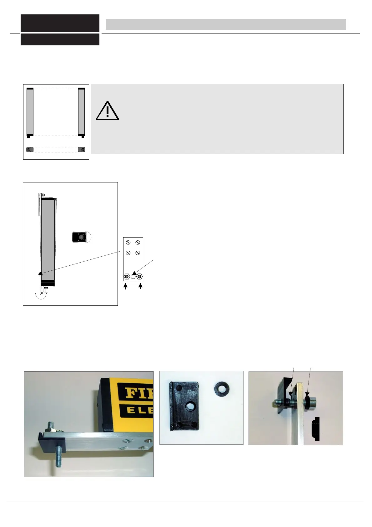
The swivel the longitudinal axis, turn the respective adjusting screw on one of the
fastening brackets whilst both screws on the other fastening bracket are loose. To swivel
the lateral axis, turn both screws of a fastening bracket at the same time whilst both
screws on the other fastening bracket are loose.
Adjusting screws with counter nuts for swivelling along longitudinal and lateral axes.
Further adjustment information is provided in chapter 6.2, "Commissioning".
bore Ø 7 mm
for attachment of the light curtain
4 Installation - Installation of transmitter and receiver
fig19/1 Installation with parallel faces
Fig 19/2 Swivelling around longitudinal and lateral axis
Important:
In order to ensure an error-free operation, both the light transmitter and light receiver
must be attached to stable, distortion-free and face-parallel constructions. Install the
fastening brackets so that the adjusting screws remain easily accessible.
Make sure that the housing is not distorted. Otherwise a perfect visual adjustment will
not be possible. Adjust one fastening bracket whilst the adjusting screws on the other
fastening bracket are loose.
fig 19/3 standard mounting brackets mounted at the light curtain.
Lateral axis
longitudinal axis
Assembled standard mounting brackets at the
light curtain
Dimension drawing of these standard brackets see
page 12 chapter 3.8
Insulating brackets at the receiver unit
These can improve insensitivity to interference clearly during EMV con-
taminated environment.
fig 19/4 insulating plastic layers
fig 19/5 mounted brackets with insulating plastic layers
FIESSLER
E L E K T R O N I K
flange of the ring must face the inside /
the aluminium bracket.
19
Fiessler Elektronik GmbH & Co. KG
Doku Nr. 958 Stand 22.01.2018 RK
Phone: +49 (0) 711 / 91 96 97-0 Internet: http://www.fiessler.de
Fax : +49 (0) 711 / 91 96 97-50 eMail: info@fiessler.de