4.4.5 4.5 Assembly columns
For installation in an open area (e.g. for the multi-sided
protection of hazardous areas), the ULVT light barriers
and titled mirrors can supplied as premanufactured
assembly columns.
order codes (examples)
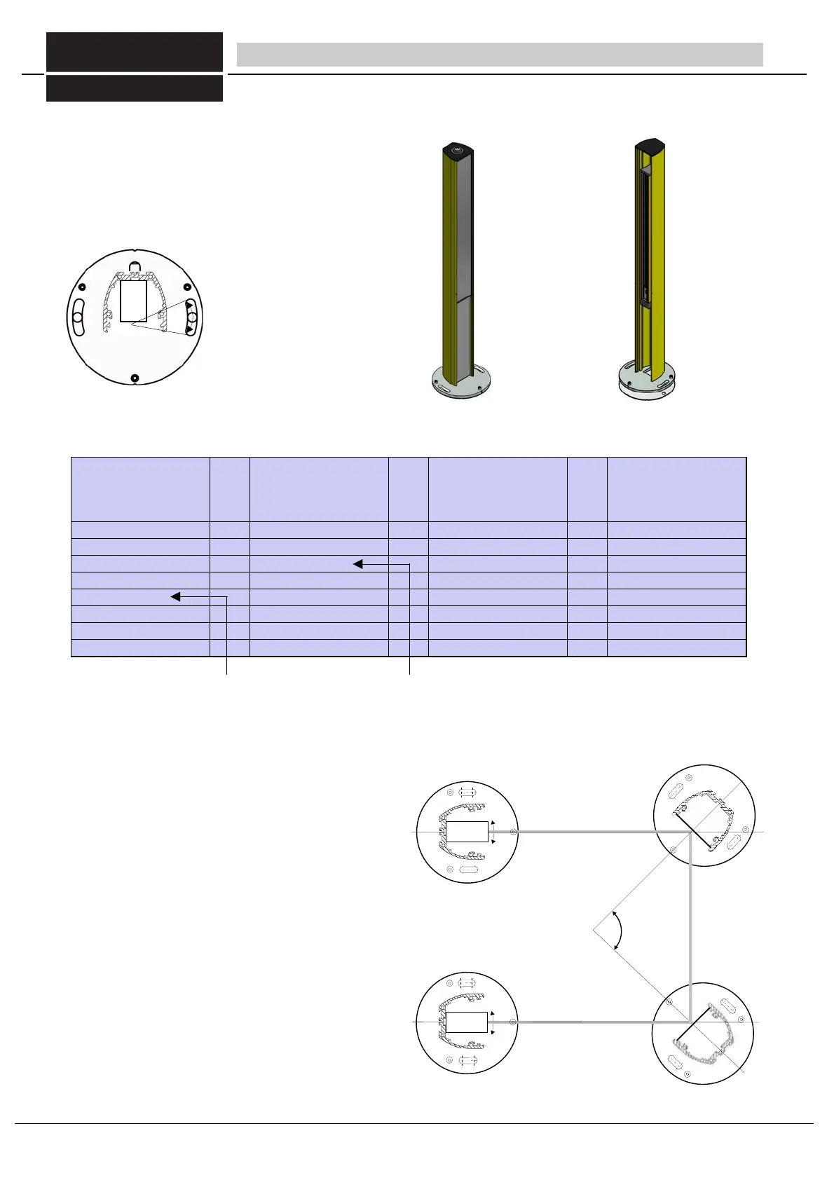
Installation of the columns
1. Provide electric connection of transmitter and receiver
2. Optically align the transmitter, receiver and mirrors
3. Check for correct function
4. Drill the holes and attach the columns
The transmitter, receiver and mirror columns are attached
vertically at the same height. A precise spirit level must be
used to check this. With vertical arrangement, the 3 adjusting
screws are used on the respective posts. The columns can
be rotated using the elongated assembly slots.
Grooves in the base plate allow to turn the base plate in an
angle of exactly 45° to each side.
This feature enables an easier adjustment of the mirror
column as well as of the mounted light curtain / light grid.
Fine tuning is carried out as described in Section 6.2,
"Commissioning".
4 Installation - Assembly columns/shock protector
fig 23/4 Installation of the columns
assemlby columns for
transmitter and receiver
including base plate
assembly columns with til-
ted mirrors
inc. Bodenausgleichsplatte
assembly columns for
transmitter and receiver
no base plate,
with 2 end pieces
assembly columns with til-
ted mirrors
no base plate,
with 2 end pieces
SAU 100
SAU 200
SASU 100
SASU 200
SDU 100
SDU 200
SDSU 100
SDSU 200
SAU 300
...
SAU 1700
SAU 1800
SASU 300
...
SASU 1700
SASU 1800
SDU 300
...
SDU 1700
SDU 1800
SDSU 300
...
SDSU 1700
SDSU 1800
SAU1900
always in 100 mm steps
SASU 1900
always in 100 mm steps
SDU 1900
always in 100 mm steps
SDSU 1900
always in 100 mm steps
for ULVT with
1700 mm
protective field h
height
for ULVT with
300 mm
protective field
height
Table 23/3 order codes
Caution: Shock-protector columns the same
as assembly columns without base plate,
but with 2 plastic covers at their ends.
fig 23/2 assembly columns for light curtains and tilted mirrors
1: Three adjustment screws for adjusting
the column
2: Two elongated mounting holes for
fastening the baseplate on the floor
and for fine adjustment of the column
(max. M12 screws)
3: Cable duct
4: Groove for fastening the light barrier by
using the brackets (brackets are inclu-
ded in delivery)
5: Fastening grooves for fastening the
column(without base plate) on a
machine or on the wall.
fig 23/1 Base plate
FIESSLER
E L E K T R O N I K
28°
2
2
23
Fiessler Elektronik GmbH & Co. KG
Doku Nr. 958 Stand 22.01.2018 RK
Phone: +49 (0) 711 / 91 96 97-0 Internet: http://www.fiessler.de
Fax : +49 (0) 711 / 91 96 97-50 eMail: info@fiessler.de