Start interlock
Subsequent to commissioning and/or a power interruption, the start interlock prevents a "re-release". A re-release is only possible
once the protective field has been interrupted and reactivated.
Response time
The time period between penetration of the protective field and the switching process.
Blanking
Ther Balnking features provide the temporarily "skipping" or "disabling" of selected areas of the the protective field. By doing this,
parts of tools or machinery may reach into the protective field without reducing the function of the machine. (please refer top
chapter 7 BLVT).
EPSE Type 4
The ULVT/BLVT... safety light barriers comprise photo-electric guards. These devices are characterized by the fact that when the
protective field generated by the transmitter and receiver is interrupted, a hazardous movement is interrupted or prevented.
One-cycle (two-cycle operating mode)
Subsequent to one (two) penetrationsof the protectvie field, the machine automatically performs an operating cycle and then waits
for a maximum 30 seconds for one (two) penetrations.
If the time period exceeds 30 seconds, the restart interlock is activated.
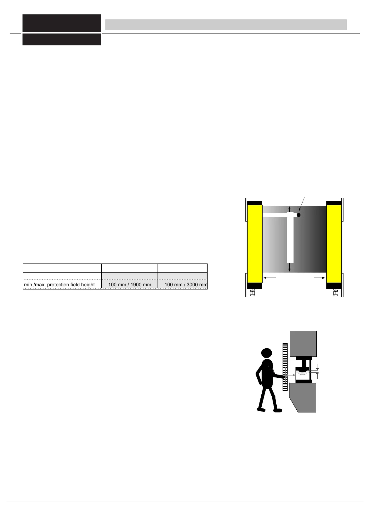
Installation range (Fig. 6/1)
The minimum and/or maximum permissible distance between the transmitter and
receiver. The permissible detection range is specified on the ULVT receiver.
Obstacle size (Fig. 6/1)
The obstacle size indicates the minimum obstacle diameter that will definitely interrupt a
hazardous movement through the safety light barriers.
The following obstacle sizes are provided by the beam distances for the ULVT... safety
light barriers:
Muting
Temporary and safe bridging of the ULVT/BLVT safety light barriers during a material movement, e.g. into and out of a
manufacturing cell, or in high-bay storage. Reliable differentiation between man and material flow is ensured.
Overrrun
The section of hazardous movement which occurs after penetration of the protective field.
Overrrun traverse (Fig. 6/2)
The path traversed during the run-on period (e.g. path of a ram, path of a point on a roller
surface).
Overrrun period
Duration of the run-on period.
Protective field height (Fig. 6/1)
Height of the protective field generated by the transmitter and receiver.
Safety mode
When the protective field is interrupted, the switching outputs are blocked, then automatically released subsequent to re-release
of the protective field.
Self-monitoring
The automatic response of the photo-electric guard in the event of an internal malfunction.
Safety distance (Fig. 30/2)
The minimum distance S between safety light barrier and the nearest hazardous area, required in order to prevent injuries. In
order to establish the minimum safe distance, the formulas from standard EN 999 / ISO 13855, the machine-specific EC
standards and the effective ZH guidelines are to be used.
min./max. detection range 0,3 m / 7 m 0,3 m / 24 m
min. obstacle diameter
min./max. protection field height
14 mm
100 mm / 1900 mm
30 mm
100 mm / 3000 mm
2 Terminology
protective field height
detection range
obstacle diameter
Bild 6/2 Ssafety distance and overrun traverse
fig 6/1 detection range, obstsacle size, protective fied height
Table 6/1a detection range, obstsacle size, protective fied height
Overrun
traverse of
the machine
FIESSLER
E L E K T R O N I K
6
Fiessler Elektronik GmbH & Co. KG
Doku Nr. 958 Stand 22.01.2018 RK
Phone: +49 (0) 711 / 91 96 97-0 Internet: http://www.fiessler.de
Fax : +49 (0) 711 / 91 96 97-50 eMail: info@fiessler.de