7 BLVT-blanking functions -safety advices
7.1 aditional safety advices for the BLVT
a. admissibility of the application: The various blanking features and their admissibility to the different operating modes must be thoroughly che-
cked before their application. The light curtain BLVT combined with the programmer BLPG provides the various blanking functions. The admissibility of
each application must be individually checked. This check of admissibility must also include if and how protection of the blanked sectors might be possi-
ble by additional mechanical protective measures, and the condition of the installation at the machine. The safety of the individual construction must be
verified by an expert.
b. mechanical protective measures: additional mechanical protective devices besides the blanked machinery parts must be controlled by position
switches as an integrated part of the safety chain, or, they must be fixed so that they cannot be removed by the use of regular tooling.
c. response time: compared to the light curtains ULVT, the response time of the BLVT is slightly longer. See chapter 4.1, page 13.
d. Programming the blanking functions: On special demand, Fiessler Elektronik pre-programs each desired blanking pattern before delivery, or the
customer himself may program the desired blanking patterns by using the programmers PLSG, BLPG and BPSG. See page 56. Programming of the
blanking patterns must be carried out by authoirized personnel only. This must be guaranteed by the use of a key-operated switch, provided by the cu-
stomer. This key must be kept separately from the installation at a secured place in order to prevent unauthorized personnel from illegal pro-
gramming. Having completed the programming procedure, the machine must not go into operation by itself. If the start interlock / restart interlock fea-
ture is not present within the light curtain, it must be realised within the next higher control .
e. Location of the key switch: The key switch must be installed at the machine in a position from which there is an unobstructed view onto the whole
protective field.
f. After re-programming or after an exchange of the receiver, pass the corresponding test rod through the complete protective field for
check. When doing so, make sure that the test rod is moved directly in front of the transmitter window, then close to the receiver window and then right
in the middle of the protecting field between transmitter and receiver. (see fig. 29.4). During this test, neither the green LED nor the yellow LED must light
up. By doing this, possibilities of the system failing to detect an obstrusion as a result of reflection from some reflective objects in the programmed blan-
ked areas are excluded.
g. Indication of the current resolution and of the protective field: The current resolution must be marked on special labels on the light curtain. If
the light curtain is cleared, the blanking pattern "Reduced resolution" or "Floating Blanking" is indicated by the flashing of the yellow LED for "restart in-
terlock" and the orange LED for "adjustment" at a frequency of 1Hz. A reduced resolution will effect the safe distance and must be drawn into its calcu-
lation accordingly.
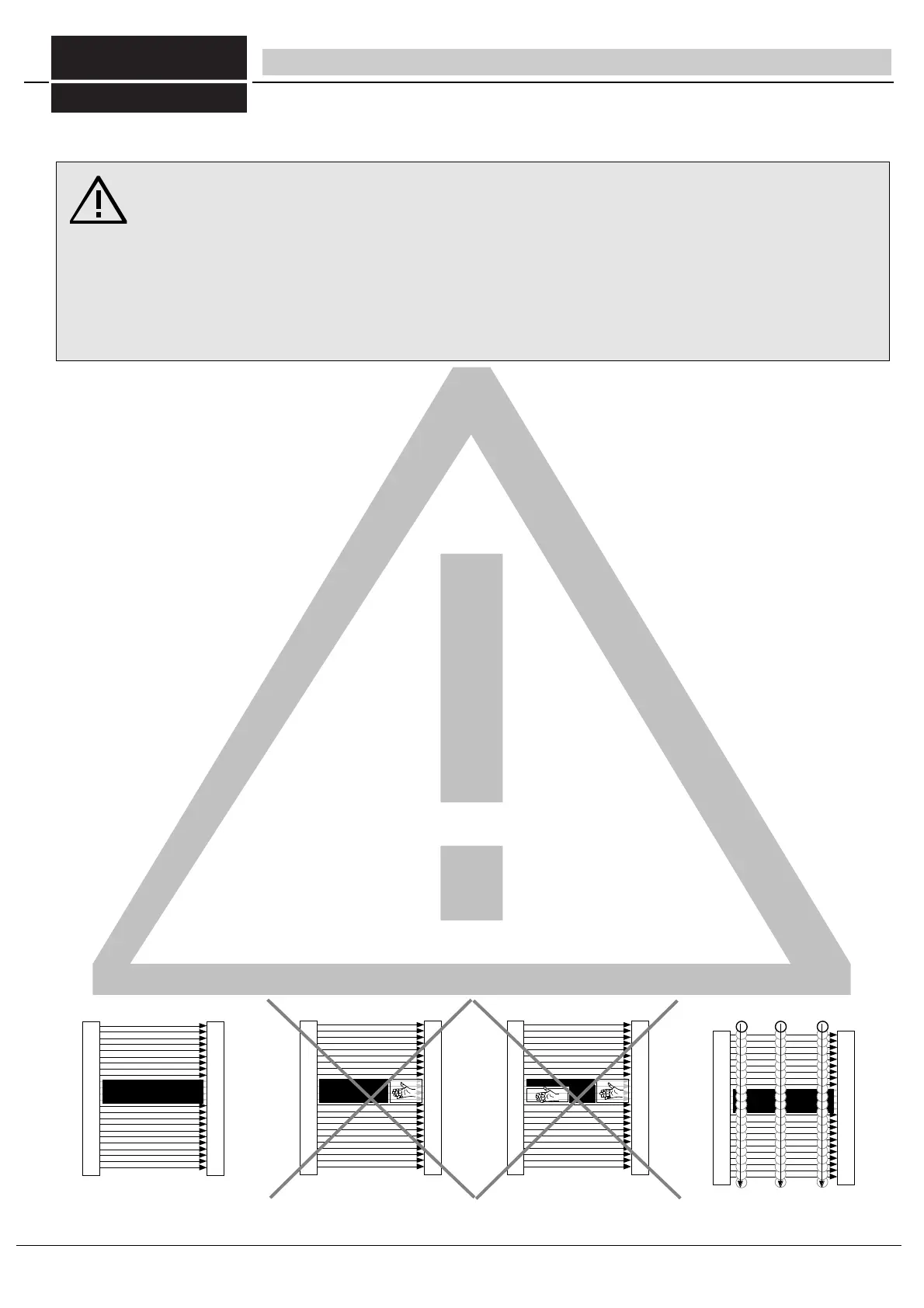
h. The Blanking must cover the whole protective field width in order to prevent any reaching into the field by the operator. (see fig. 29.1, 29.2, and 29.3).
all safety advices as stated in chaper 1 and in chapter 8 must be strictly observed!
Any incorrect use of the blanking features, i.e. their inappropriate integration into the function of the machine
represent a potential danger. Therefore, the prerequisites for the use of the blanking function that are descri-
bed in this instruction manual, must be thoroughly understood and strictly observed.
Normally, additional mechanical protective means are required in order to prevent machine operators from reaching
into the hazardous area, getting past the blanked machinery parts.
Certain precautions must be taken in order to stop the machine if the additional mechanical protective means are re-
moved from their place.
fig. 29.2 Fixed Blanking or Floating Blanking
with only partial utilization of the blanked sec-
tor of the light curtain. Additional covering is re-
quired.
fig 29.3 Fixed Blanking or Floating Blanking
with only partial utilization of the blanked
sector of the light curtain. Additional covering
is required.
fig 29.4 passage of a corresponding test rod
through the whole protective field
fig 29.1 Fixed Blanking or Floating Blanking
with full utilization of the blanked sector of the
light curtain.
not allowed!
not allowed!
FIESSLER
E L E K T R O N I K
29
Fiessler Elektronik GmbH & Co. KG
Doku Nr. 958 Stand 22.01.2018 RK
Phone: +49 (0) 711 / 91 96 97-0 Internet: http://www.fiessler.de
Fax : +49 (0) 711 / 91 96 97-50 eMail: info@fiessler.de