8.5 Response times of cascaded light grids
The cascadable light grids detect any interruption of the protection field of the secondary (="slave") sensor wit-
hin 3ms. The response time of the respective light grids is obtained by adding the individual response time to 3ms for
each preceeding light grids.
Master sensor individual response time (as shown on the type plate)
Slave sensor1 individual response time + 3 ms
Slave sensor2 individual response time + (2 x 3 ms = 6 ms)
The own response time is stated oon the type plate of the respective light grid.
The table on page 13 shows the individual response times for all standard light grids.
8 Cascading of Light Grids -Response times / Safety distances
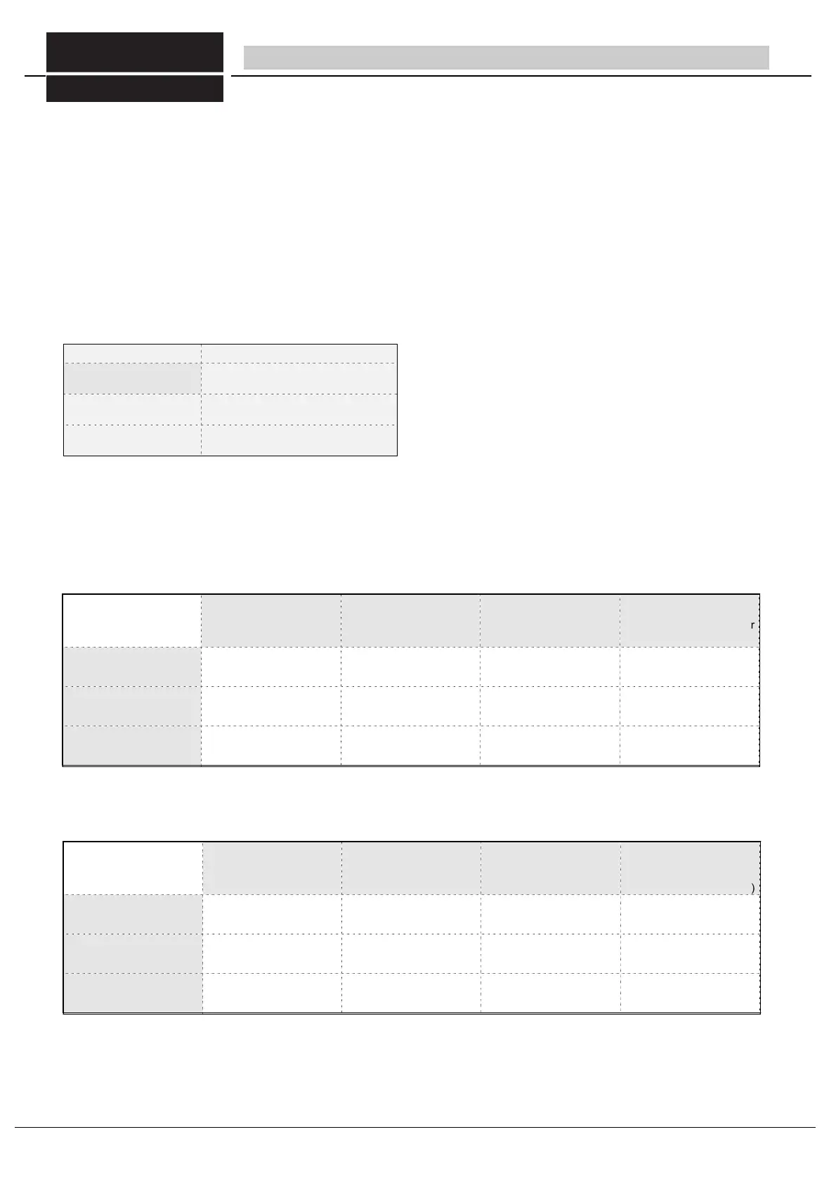
Table 35/1 response times cascadable light curtains
Master sensor
ULVTK 500/65
Slave sensor1
ULVTK 500/35
Resolution
see tables page 13
individual response
time of the light grid,
see tables page 13
safe distance
(Formula: refer to chapter
4.2.1)
Master sensor
ULVTK 500/65
slave sensor 1
ULVTK 1500/195
14 mm (C= 0 mm)
14 mm (C= 0 mm)
10 ms
21 ms
same as individual re-
sponse time= 10 ms
slave sensor 2
ULVT 500/35
S = 176 mm + 128 mm =
304 mm
Tabllelle 35/2 calculation example safe distance of cascaded light grids
Table for calculating of the respective response times of your utilized cascaded light grids :
resolution
s. tables S. 13
individual response
time of the light grid,
see tables page 13
safe distance
(Formula: refer to chap-
ters 4.2.1, 4.2.2. or 4.2.3)
S = ..............mm
S = .............. mm
Tabelle 35/3
8.6 safe distance of cascaded light grids
When calculating the safe distance of the light grids (refer to chapter 4.2), it must be considered that each preceding light
grid will increase the response time of the cascaded light grid by 3ms.
Calculation example:
FIESSLER
E L E K T R O N I K
35
Fiessler Elektronik GmbH & Co. KG
Doku Nr. 958 Stand 22.01.2018 RK
Phone: +49 (0) 711 / 91 96 97-0 Internet: http://www.fiessler.de
Fax : +49 (0) 711 / 91 96 97-50 eMail: info@fiessler.de