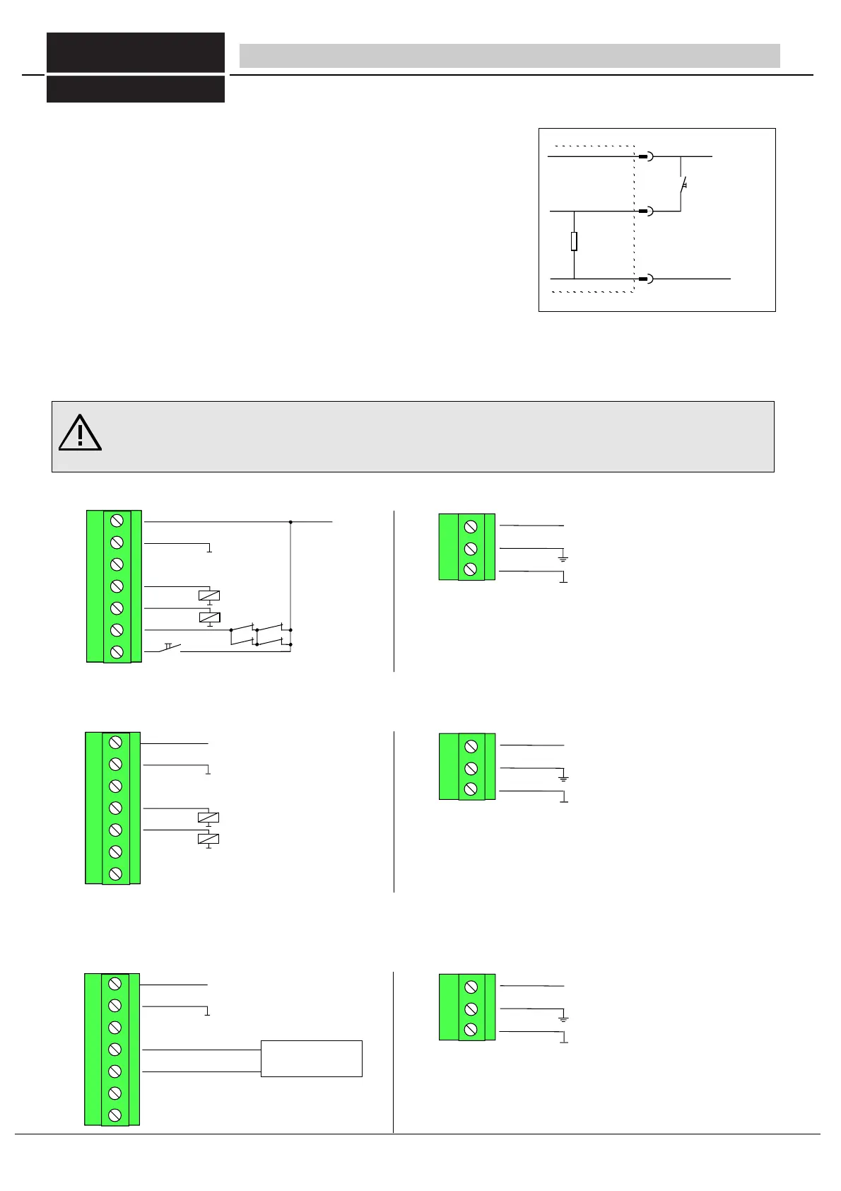
- Input start button
If the operating mode with restart interlock is set, a button must be connected on
the start button input for the start release of the operating movement (Fig. 26/1).
With a free protective field, the yellow LED on the receiver lights up as a start
prompt. Only once the start button has been pressed will the two outputs OSSD1 and
2 of the ULVTE receiver be switched to active.
If the operating mode without restart interlock is set, the start button input (start)
must be unoccupied).
5.4 Connection examples (without the additional function such as Muting or
cycle mode, please refer to the operation manual of the respective switching unit)
5.4.2 Operating mode with restart interlock / contactor control
5.4.3 Operating mode without restart interlock / contactor control
5.4.4 PLC drive
When connecting to a safe stored program control (PLC) the outputs of the ULVT/BLVT must be connected
to separate inputs of the PLC
5 Electric connection - Connection of receiver and transmitter
Caution! Error-free operation can only be ensured when the safety light barrier is connected according to one of the
following connection diagrams and also complies with effective national and international accident prevention regula-
tions!
Any deviation from these connection specifications can lead to hazardous conditions and is therefore not permitted.
0V
7
1
+24V DC±20%
Start-Taster
6
Eingang Start-Taster
fig. 26/1 input start button
+24V DC± 20%
Start- Taster
Eingang Start- Taster
receiver
transmitter
receiverr
transmitter
receiver
transmitter
+24V DC ± 20%
0V
OSSD2
OSSD1
contactor control
start button
+24V DC ± 20%
0V
OSSD2
OSSD1
unoccupied
unoccupied
+24V DC ± 20%
0V
OSSD2
OSSD1
unoccupied, if contactor control is done by the safety PLC
unoccupied, if contactor control is done by the safety PLC
Safety PLC
+24V DC + 20% -10%
functional ground
0V
+24V DC + 20% -10%
functional ground
0V
+24V DC+ 20% -10%
functional ground
0V
fig 26/2
fig 26/3
5.4.1 There is no need of a connection of the light transmitter at the light grid ULVT 500/2R, because the transmitter is in-
tegrated in the receiver unit.
E2
E1
fig 26/4
FIESSLER
E L E K T R O N I K
26
Fiessler Elektronik GmbH & Co. KG
Doku Nr. 958 Stand 22.01.2018 RK
Phone: +49 (0) 711 / 91 96 97-0 Internet: http://www.fiessler.de
Fax : +49 (0) 711 / 91 96 97-50 eMail: info@fiessler.de