5.1 Integrated connector plug
The ULVT/BLVT construction series is supplied with PG
threaded joints as standard. Various conventional
connector plugs can also be obtained as optional
accessories.
The electric connection is implemented via terminal screws
in the connector cover (Fig. 25/1). The cover can be
removed once the 4 screws have been loosened.
The transmitter and receiver require a power supply of 24
V DC. The ULSG switchgear performs the power failure
bridging of 20 ms pursuant to EN 60204 and is thus suitable as the power supply for ULVT/BLVT light barriers. The receiver is
equipped with 2 inputs and 2 outputs. The transmitter is connected via one 3-pin cable and the receiver via one 5 to 7-pin
cable (depending on operating mode). The permissible cable cross-section is max. 1.5 mm2. The cables must be routed
separately from power lines.
5.2 Electric connection ratings
5.3 Connectors
- Outputs 1 and 2 (OSSD 1 and OSSD 2)
The outputs are not potential-free and must not be switched in series
or parallel, but must be connected and processed separately!
In the operating mode with equivalent outputs, both PNP outputs are
failsafe and feature internal short-circuit and cross-circuit monitoring. Both
outputs are high (+24 V) when the light path is free.
In the operating mode with antivalent outputs, output 1 is high (+24 V)
and output 2 low (0 V) when the light path is free. Output 2 is not failsafe
in this operating mode. This operating mode is only permissible in
conjunction with the safety switchgears LSUW NSR 3-1K, LSUW N1-
Muting K, or another safe sequential phase control device which
monitors output 2!
- Input contactor check (EDM)
If the operating mode with contactor check is set, the auxiliary contacts
K1 and K2 of the driven contactors K1 and K2 must be connected to the
contactor check input in series and with +24 V as shown in Fig. 25/4.
The OSSD1 and OSSD 2 of the ULVT will only switch on the two contactors
when contactor check input has detected the idle status of the contactors (+
24 V at contactor check input).
Once the contactors have been driven, both of them must respond within
300 ms. The two auxiliary contacts must then be open (0 V at contactor
check input).
If the operating mode without contactor check is set, the input contactor
check must be unoccupied.
5 Electric connection - Connection of receiver and transmitter
The electric connection must only be carried
out when no voltage is present.
OSSD 2
OSSD 1
3
4
7
+24V DC±20%
0V
6
K 1 K 2
fig 25/3 outputs 1 and 2
0V
7
2
+24V DC±20%
Eingang Schützkontrolle
6
Hilfsöffner k1
Hilfsöffner k2
fig 25/4 input contactor control
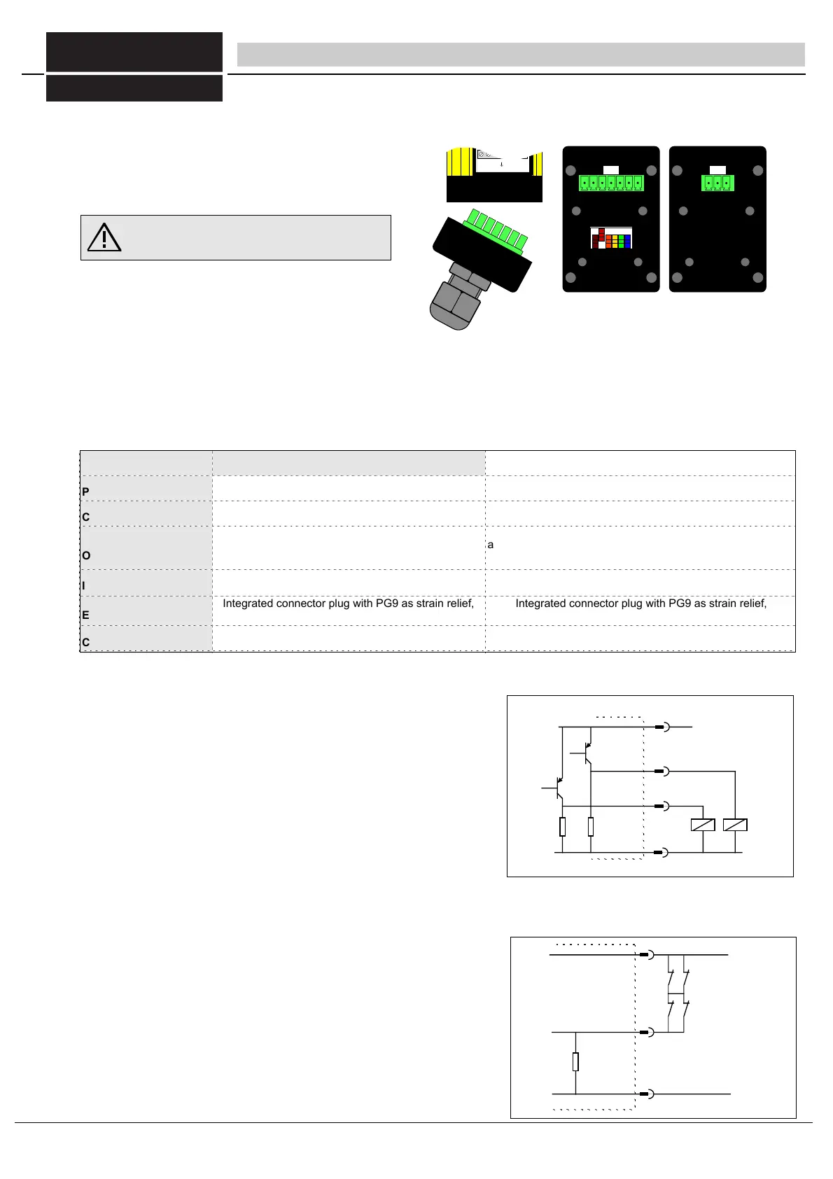
123 4 56 7
3: OSSD1
5:
2: EDM
7: 24VDC
±20%
4: OSSD2
1: Start
123456
off
12 3456
7
1
2
3
6: 0V
fig. 25/1 Integrated connector plug with terminal screws in connector
cover Receiver 7-pin, transmitter 3-pin.
+24V DC± 20%
auxiliary contact k1
auxiliary contact k 2
input contactor control
Table 25/2 electri connection ratings
ULVTS/BLVTS transmitter ULVTE/BLVTE receiver
Power supply
Current draw
24 V DC, + 20% - 10%, SELV
max. 250 mA
24 V DC, ±20%, SELV
max. 250 mA (without load)
Outputs
Inputs
Electric connection
Connecting cable
-
-
OSSD 1 and 2: Failsafe PNP outputs,max. 0.5 A, short-circuit
and cross-circuit monitoring (in operating mode with antivalent
outputs, output 2 is a non-failsafe PNP output, max 20 mA
)
Inputs contactor check and start button:
0 V to 24 V DC _+ 20%, 10 mA
Integrated connector plug with PG9 as strain relief,
alternatively conventional connector plug.
Integrated connector plug with PG9 as strain relief,
alternatively conventional connector plug.
5 to 7-pin (depending on operating mode) max. 1.5 mm2
Protection category IP 65 IP 65
FIESSLER
E L E K T R O N I K
25
Fiessler Elektronik GmbH & Co. KG
Doku Nr. 958 Stand 22.01.2018 RK
Phone: +49 (0) 711 / 91 96 97-0 Internet: http://www.fiessler.de
Fax : +49 (0) 711 / 91 96 97-50 eMail: info@fiessler.de