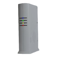
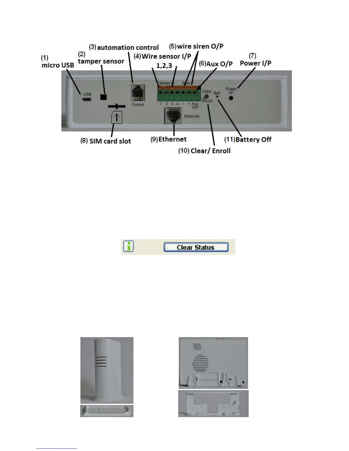
1.2 Rear Panel:
(1). micro USB: Connect to PC for accessing from HyperSecureLink software.
(2). tamper sensor: for tamper detection (Only for wall mounting bracket.)
(3). automation control: RJ-9 connector for X-10 control interface.
(4). 3 wire sensor input terminals.
(5). wire siren output terminals.
(6). Aux output: for Arm/Disarm indication (only driver LED )
(7). Power Socket: 7V DC power input.
(8). SIM Card slot: For GSM SIM card (only for the GSM/GPRS version)
(9). RJ-45 Ethernet Socket: Connect to the Ethernet network.
(10). Clear/Enroll Button:
Clear LED Status: Press the button for about 0.2 sec. to clear the alarm and warning LED status.
The LED status also can be cleared from HyperSecureLink command.
Device Enroll: Press the button for about 3 sec. the LS-20 enters into Enroll Device State for
30 seconds. (Buzzer beeps and Green, Yellow, Red LEDs flash)
Please refer to Section 4.1.
(11). Battery Off: Stick in a straightened paper clip to turn off the battery when the main power input
has been removed. (Note: The back-up battery starts to charge automatically while
power on.)
1.3 Mounting Bracket:
LS-20 can sit on a stand vertically or put in a wall mounting bracket as below.
Base Unit Stand Wall Mounting Bracket (option)