FINEPLACER
®
lambda
Rev-Nr. 1.1
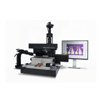
3.2.2 Support Arm (71), holding the following parts:
• Vision/observation devices, basically consisting of the stationary mounted
beam splitter optics (30), providing the dual image overlay, and a video option
for vertical view, are used to view the super-imposed image of the substrate's
pads and the corresponding component leads.
• Lighting: COAX-Illumination and diffuse illuminationis standard, a Target
Fínder (AC1) is integrated.
• The pivot bearing for the pivot arm (27). Zero play of the bearing and stiffness
of the arm are fundamental for the lambda's outstanding placement accuracy.
• The connector for electromagnet, and air for the table (4).
• The adjustment means for beam splitter (31), (32), arm-UAP (72) and arm-
LAP (89).
• Target Finder (AC1), pointing to the placement area (TARGET) on the
substrate.
• Optional: Force Applicators (e.g. FD2).
3.2.3 Pivot Arm (27)
The pivot arm may be e.g. a pivot arm (27); further special arms are available, e.g.
FE1. for ultrasonics application (chip bonding). Pivot arms have their own cables and
hoses for energy transportation and control. Each arm is equipped with a hose for
the vacuum holding the component to be placed in the positioning head, e.g. (20),
and signal cabling for arm tilt switch. The tilt switch sensing the arm position,
(erected or laid down), influences many equipment functions, e.g. switching vacuum
by pipette.
The arm is only mounted to the pivot log by 2 screws (148) so it may be changed
easily if required.
Fine-θ-Adjustment-pivot arms are available.
Attention: Pivot Arm Interlock (for manual configurations)
For FINEPLACER
®
lambda systems in manual configuration, a specific magnetic
interlock mechanism ensures that the pivot arm can only be swivelled down as long
as the optics shifting is in swivel position.
This safety function prevents the pivot arm from swivelling down and possibly hitting
and damaging the optics while the optics shifting is not in swivel position.