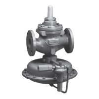
Types 1098-EGR and 1098H-EGR
10
Supply the boiler pilot light gas with the Type 1098-EGR.
The pilot light gas supply line should branch off the
main fuel line downstream of the Type 1098-EGR and
include a separate regulator to control the nal pilot
light gas pressure, if required (see Figure 5). This
allows the Type 1098-EGR to have its main valve plug
just off the seat waiting for the sudden negative shock
created when the boiler solenoid valve is opened to
light the boiler to the low re load. This installation
practice signicantly increases the stroking speed of
the Type 1098-EGR. See Figure 5 for schematic.
SIZE CONSTRUCTION ORIFICE SPRING RANGES
SPRING
NUMBER
SPRING
COLOR
MINIMUM PRESSURE
AT WHICH AUXILIARY
PILOT CAN BE SET
3/4-inch
(19 mm)
Type Y600AM
1/2-inch
(13 mm)
4 to 8-inches w.c. (10 to 20 mbar) 1B653827052 Red
1-inch w.c. (2 mbar) Under
working pilot setpoint
7 to 16-inches w.c. (17 to 40 mbar) 1B653927022 Olive Drab
15-inches w.c. to 1.2 psi (37 mbar to 0,08 bar) 1B537027052 Yellow
Type Y600AM
1/2-inch
(13 mm)
1.2 to 2.5 psi (0,08 to 0,17 bar) 1B537127022 Light Green
0.2 psig (0,01 bar) Under
working pilot setpoint
2.5 to 4.5 psi (0,17 to 0,31 bar) 1B537227022 Light Blue
4.5 to 7 psi (0,31 to 0,48 bar) 1B537327052 Black
Type 627M
1/2-inch
(13 mm)
5 to 10 psi (0,35 to 0,69 bar) 10B3076X012 Yellow
0.3 psig (0,02 bar) Under
working pilot setpoint
Table 6. Auxiliary Pilot Selection (Fast Stroke Dual Pilot)
Note
Modulating solenoid load valves provide
one position to the other, effectively
preventing sudden pressure changes in
the system. Alternately, a snap-acting
solenoid valve can be furnished with a
characterized valve plug that, by allowing
maximum capacity to be reached at a
greater proportion of total travel, slows
the action slightly. This action does
not control shock as effectively as
modulating solenoid valves.
Installation
1. Perform the Standard Single-Pilot Regulator
Installation section through step 3, making sure
that the regulator is installed with the actuator
below the main valve as shown in Figure 4.
2. Run a 1/2-inch (13 mm) or larger pilot supply
line from the upstream pipeline to the 1/2-inch
NPT supply connection in the pipe tee as shown
in Figure 4. Do not make the connection in a
turbulent area, such as near a nipple, swage, or
elbow. If the maximum pilot inlet pressure could
exceed the pilot rating, install a separate regulator
in the pilot supply line, and provide vent valves so
that pressure can be properly isolated and relieved
from the regulator.
3. Attach a 1/2-inch NPT downstream
pressure control line ten pipe diameters
downstream of the regulator in a straight run
of pipe. Do not make the tap near any elbow,
swage, or nipple, which might cause turbulence.
E0711
Figure 5. Boiler Fuel Conguration
TYPE 1098-EGR SIZE 70
WITH QUICK OPENING CAGE
20 PSI (1,4 bar) MAXIMUM
TYPE Y600AM
AUXILIARY PILOT
TYPE 6352
WORKING PILOT
 Loading...

