Types 1098-EGR and 1098H-EGR
15
for damage during normal operation by line pressure
leakage or unexpected grease extrusion from the
actuator vent (key 27, Figure 14). All O-rings, gaskets,
and seals should be lubricated with a good grade of
general-purpose grease and installed gently rather
than forced into position. Be certain that the
nameplates are updated to accurately indicate any eld
changes in equipment, materials, service conditions, or
pressure settings.
!
WARNING
To avoid personal injury resulting
from sudden release of pressure,
isolate the regulator from all pressure
and cautiously release trapped
pressure from the regulator before
attempting disassembly.
Design Type EGR Main Valve
Replacing Quick-Change Trim Package
Perform this procedure if the entire trim package
is replaced. Key numbers for both the complete
main valve and its trim package are referenced in
Figures 12 and 13. Some replacement trim package
assembly numbers are listed in a table in the parts list.
Note
All disassembly, trim change, and
reassembly steps in this section may be
performed with the regulator in the main
line and without disconnection pilot
supply or control lines.
1. Remove the cap screws (key 3) with a cast iron
body or remove the hex nuts (key 29, not
shown) with a steel body. Pry the body ange
(key 2) from the valve body (key 1) and lift out the
trim package.
2. Perform any required inspection, cleaning, or
maintenance on the exposed surfaces of the valve
body or trim package. Replace the gasket (key 4)
or cage O-ring (key 17) as necessary.
3. On a pre-built replacement trim package, check
indicator zeroing by unscrewing the indicator
protector (key 19) and seeing if the ange of
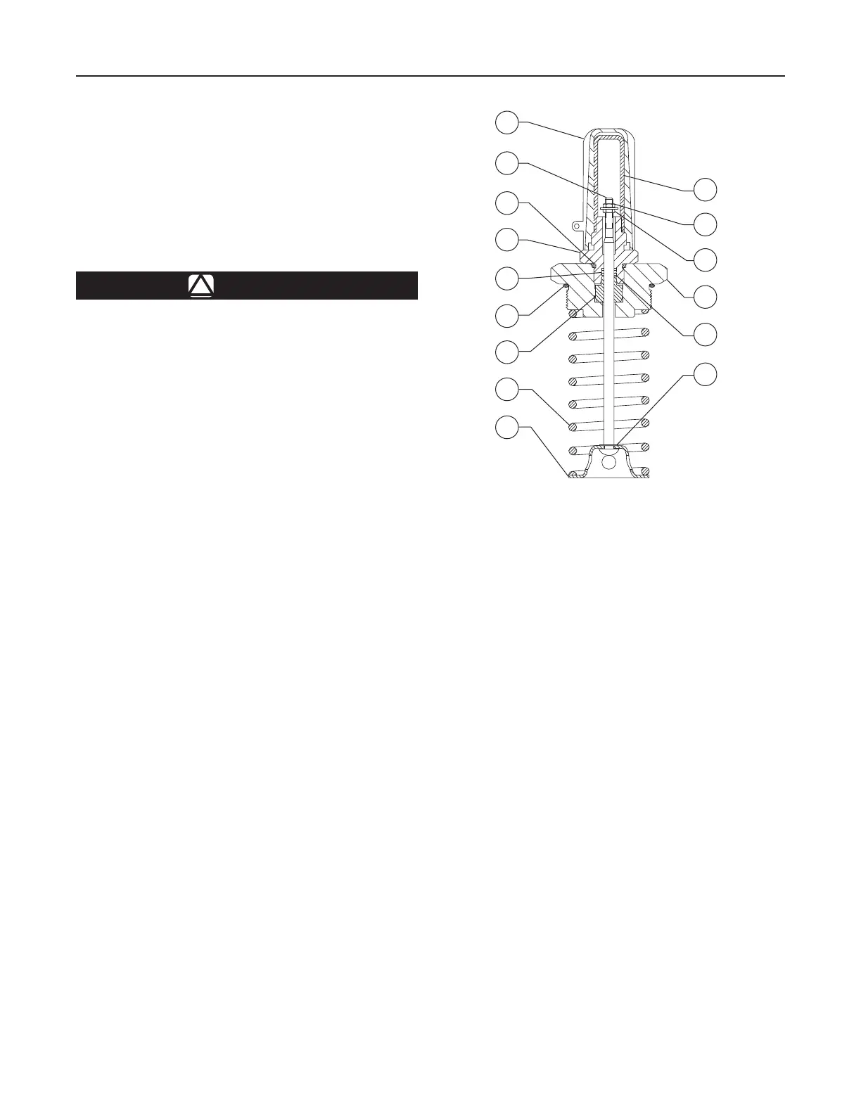
10C1212
Figure 11. Types 1098-EGR and 1098H-EGR Travel
Indicator Assembly
the indicator nut (key 22) lines up evenly with
the bottom marking on the indicator scale
(key 18). If not, remove the indicator scale
and separate the indicator nut and hex nut
(key 8). Hold the indicator scale against
the indicator tting (key 5) with the scale base
resting against the shoulder of the tting, and
turn the indicator nut until its ange is aligned
with the bottom scale marking. Then lock both
nuts against each other, and install the indicator
scale and protector.
4. Coat the cage seating surface of the valve body
web and the body ange seating surfaces of the
valve body neck with a good grade of general-
purpose grease. Install the trim package, and
secure it evenly with the cap screws or stud
bolt nuts.
No particular trim package orientation in the body
is required.
19
10
37
35
7
21
6
9
28
23
36
5
8
22
18

 Loading...


