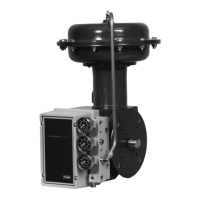
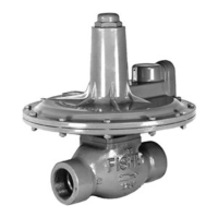
Types 1098-EGR and 1098H-EGR
21
numbers are referenced in Figure 14, and mounting
part numbers in Figure 28, unless otherwise indicated.
1. The actuator and pilot(s) may be removed and
replaced as a unit by disconnecting the control
line and pilot supply line.
2. Access to all internal parts except the stem
O-rings, bearings and wiper (keys 6, 56, 57) may
be gained without removing the bonnet (key 3) or
upper diaphragm case (key 2) from the main valve
or the pilot(s) from the bonnet pipe nipple
(key 23, Figure 25, or keys 37 and 39, Figure 29).
Disconnect the loading tubing (key 24,
Figure 25, 27, or 29) from the actuator elbow tting
(key 25, Figure 25, or key 41, Figure 29), and with
a Type 61LD pilot also disconnect the relief tubing
(key 18, Figure 26) from the tting tee.
3. Remove the cap screws (key 10), nuts (key 11),
lower diaphragm case (key 1), diaphragm (key 7),
and diaphragm plate (key 8). To separate the stem
(key 12) from the diaphragm plate (key 8), remove
the stem cap screw (key 9).
4. To remove the Type 1098 case O-ring
(key 5), unscrew the four case cap screws
(key 4), remove the upper diaphragm case
(key 2), and remove the case O-ring.
To remove the Types 1098 and 1098H stem
O-rings (key 6), remove the pilot(s) and pipe
nipple(s) if necessary. Unscrew either the
Type 1098 bonnet (key 3) or the Type 1098H
upper diaphragm case (key 2), and remove the
wiper ring, bearings, and O-rings.
5. Lubricate both stem O-rings (key 6) and wiper ring
(key 57) and install them with the stem bearings
(key 56) in either the Type 1098 bonnet (key 3) or
in the Type 1098H upper diaphragm case (key 2).
For the Type 1098H actuator, thread the upper
diaphragm casing into the main valve body.
For the Type 1098 actuator, lubricate the case
O-ring (key 5), and install it in the bonnet (key 3).
Line up the holes in the upper diaphragm casing
and the bonnet; insert and tighten the four case
cap screws to secure the parts together. Thread
the bonnet into the main valve body.
6. Secure the diaphragm plate to the stem with
the stem cap screw (key 4). Lay the entire
diaphragm, diaphragm plate, and stem
assembly into the lower diaphragm case so the
diaphragm convolution laps up over the
diaphragm plate according to Figure 14. Then
install the stem slowly up into the bonnet to
prevent stem or O-ring damage, and
secure the lower diaphragm case to the upper
diaphragm case with the cap screws
and nuts. Tighten the cap screws and nuts
evenly in a crisscross pattern to avoid crushing
the diaphragm.
7. Grease the stem O-rings through the zerk
tting (key 28) until excess grease emerges from
the vent (key 27).
8. Install the pipe nipple(s) and pilot(s) if they were
removed during maintenance. Connect the
actuator loading tubing if it was disconnected.
Parts Ordering
Each Type 1098-EGR or 1098H-EGR regulator is
assigned a serial number or FS number which can be
found on the nameplates. Refer to this number when
contacting your local Sales Ofce for assistance, or
when ordering replacement parts.
When ordering a replacement part, be sure to
include the complete 11-character part number from
the following parts list. Some commonly used trim
packages can be ordered according to the 11-character
assembly number given in the parts kits listed in the
Parts List.
Parts List
Note
Except where indicated, sizes shown are
valve body sizes.
 Loading...

