Types 1098-EGR and 1098H-EGR
14
3. Slowly open the hand valve in the control line
and adjust the pilot setting if necessary. Set
the monitoring regulator at a slightly higher control
pressure than the working regulator.
4. Completely open the downstream block valve.
5. Slowly close the bypass valve, if any.
Shutdown
Installation arrangements vary, but in any installation it
is important that the valves be opened or closed slowly
and that the outlet pressure be vented before venting
inlet pressure to prevent damage caused by reverse
pressurization of the pilot or main valve. The following
steps apply to the typical installation as indicated.
Single-Pilot, Dual-Pilot Regulator, or
Wide-Open Monitor
As well as applying to a single-pilot regulator (Figure 3),
the steps in this procedure also are valid for a dual-
pilot regulator (Figure 4), or a wide-open monitoring
installation (Figure 8) and just need to be repeated for
each regulator in such an installation.
1. Slowly close the downstream block valve. If the
control line is downstream of the block valve, also
close the hand valve in the control line.
2. Slowly close the upstream block valve and the
hand valve in the pilot supply line.
3. Slowly open the vent valve in the downstream
pipeline. If the control line is downstream of the
block valve, also open the vent valve in the control
line. Permit all pressure to bleed out.
4. Slowly open the upstream pipeline vent valve.
Allow all pressure to bleed out of both the piping
and the pilot.
Working Monitor
1. Slowly close the downstream block valve and the
hand valve in the downstream pressure control line.
2. Slowly close the upstream block valve and the
hand valves in both pilot supply lines.
3. Slowly open all vent valves and permit all pressures
to bleed out of the piping and regulators.
Maintenance
Regulator parts are subject to normal wear and must be
inspected and replaced as necessary. The frequency
of inspection and replacement of parts depends upon
the severity of service conditions or the requirements
of local, state, and federal regulations. Due to the care
Fisher
®
takes in meeting all manufacturing requirements
(heat treating, dimensional tolerances, etc.), use only
replacement parts manufactured or furnished by Fisher.
The stem O-rings on the Type 1098 or 1098H actuator
can be lubricated annually, using the grease tting
(key 28, Figure 14). Stem O-rings can be checked
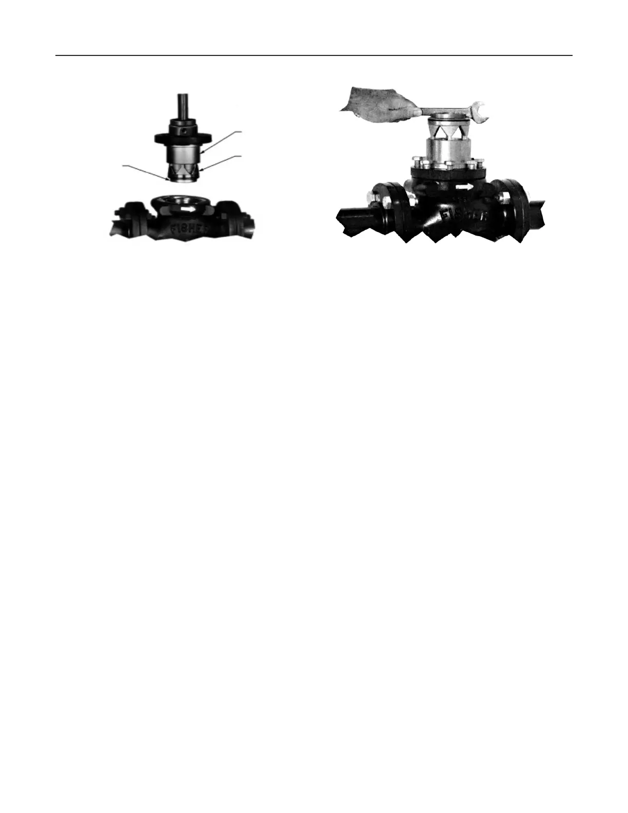
Figure 10. Seat Ring/Cage Removal or Installation
Using Body as Holding Fixture
W2772-1
BODY FLANGE
W3012-1*
SEAT RING
SCREWS INTO CAGE
CAGE SCREWS INTO
BODY FLANGE
Figure 9. Trim Package Removal

 Loading...


