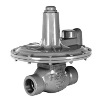
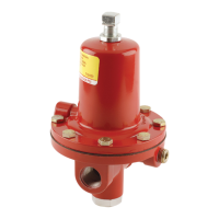
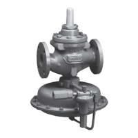
Types 1098-EGR and 1098H-EGR
7
elaborate venting systems. This regulator can also be
installed in pits subject to ooding by venting the pilot
spring case above the expected ood level so that the
pilot diaphragm is exposed to atmospheric pressure.
Note
Normal pressure drop assists shutoff.
Therefore, leakage may result during any
reverse pressure drop condition.
1. Use qualied personnel when installing, operating,
and maintaining regulators. Before installing,
inspect the main valve, pilot, and tubing for any
shipment damage or foreign material that may
have collected during crating and shipment. Make
certain the body interior is clean and the pipelines
are free of foreign material. Apply pipe compound
only to the male pipe threads with a screwed
body, or use suitable line gaskets and good
bolting practices with a anged body.
With a weld end body, be sure to remove the
trim package, including the gasket, according
to the Maintenance section before welding
the body into the line. Do not install the trim
package until any post-weld heat treatment is
completed. If heat treating, prevent scale
build-up on all machined guiding and sealing
surfaces inside the body and at the bonnet
ange/body joint.
Note
the valve body.
2. Install a three-valve bypass around the regulator
if continuous operation is necessary during
maintenance or inspection. The pilot may be
eld-changed to the opposite-side mounting
position by swapping the pilot pipe nipple to the
opposite bonnet tapping.
!
WARNING
A regulator may vent some gas to
the atmosphere. In hazardous or
accumulate, and cause personal injury,
explosion. Vent a regulator in hazardous
gas service to a remote, safe location
away from air intakes or any hazardous
location. The vent line or stack opening
must be protected against condensation
or clogging.
3. To keep the pilot spring case vent from being
plugged or the spring case from collecting
moisture, corrosive chemicals, or other foreign
material, point the vent down or otherwise protect
it. To remotely vent the standard pilot, remove the
vent and install obstruction-free tubing or piping
into the 1/4-inch NPT vent tapping. Provide
protection on a remote vent by installing a screened
vent cap into the remote end of the vent pipe.
4. Run a 3/8-inch (9,5 mm) outer diameter or
larger pilot supply line from the upstream pipeline
to the lter inlet as shown in Figure 3. Do not
make the upstream pipeline connection in a
turbulent area, such as near a nipple, swage, or
elbow. If the maximum pilot inlet pressure could
exceed the pilot rating, install a separate reducing
regulator in the pilot supply line. Install a hand
valve in the pilot supply line, and provide vent
valves to properly isolate and relieve the pressure
from the regulator.
5. Attach a 1/2-inch NPT downstream pressure
control line downstream of the regulator in a
straight run of pipe, as shown in Figure 3.
Do not make the tap near any elbow, swage, or
nipple that might cause turbulence. Connect
the other end of the control line to the bonnet
connection. Install a hand valve in the control line
to shutoff the control pressure when the bypass is
in use.
6. If a quick acting solenoid is to be installed
downstream of the regulator, the regulator
and solenoid should be located as far apart
as practical. This maximizes the gas piping
volume between the regulator and solenoid
and improves the regulator response to quick
changing ow rates.
7. Consult the appropriate instruction manual for
installation of an optional Type 662 pneumatic
or electric remote control drive unit. For
optional remote pneumatic loading of a
6350 or 61 Series pilot, make the loading piping
connections to the 1/4-inch NPT vent connection.
Prestartup Considerations
Before beginning the startup procedures in this section,
make sure the following conditions are in effect:
• Block valves isolate the regulator.
• Vent valves are closed.
• Hand valves are closed.
 Loading...

