Fisherbrand part-number 1
List of Figures
Figure 3-1 Incubator dimensions and required clearances................................................................................................ 11
Figure 3-2 Lift Points ..................................................................................................................................................... 12
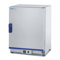
Figure 4-1. Fisherbrand Basic 60L/100L/180L Gravity Incubator Front View...................................................................... 15
Figure 4-2. Fisherbrand Basic 60L/100L/180L Gravity Incubator Rear View ...................................................................... 16
Figure 4-3. Sensor System............................................................................................................................................. 17
Figure 4-4. Basic Gravity Incubator Shelf System ............................................................................................................. 19
Figure 5-1. Sliding the Retaining Spring into the Support Rail ........................................................................................... 21
Figure 5-2. Support Rail Installation ................................................................................................................................ 22
Figure 5-3. Shelf Support Installation .............................................................................................................................. 23
Figure 5-4. Installing the Perforated Shelves.................................................................................................................... 23
Figure 7-1. Control Panel for Fisherbrand Basic Gravity Incubator ..................................................................................... 29
Figure 10-1. Door seal ................................................................................................................................................... 41