FlashCut CNC Section 5 Signal Generator
using a separate input cable. Note that if an input line is being used through the
Motor Signal connector, that line must remain open in the Input connector.
The receptacle that plugs into this connector is a Molex-Waldom Mini-Fit Jr. Series
16 pin receptacle (part number 39-01-2160), with female pins (part number 39-00-
0039 or 39-00-0047 for 22 gauge or thinner wires).
The Molex 63811-1000 for 14-24 AWG universal or Molex 11-01-0197 Crimp Tools
are recommended for installing the pins. Kits containing connectors and pins are
available through FlashCut CNC or an electronics distributor.
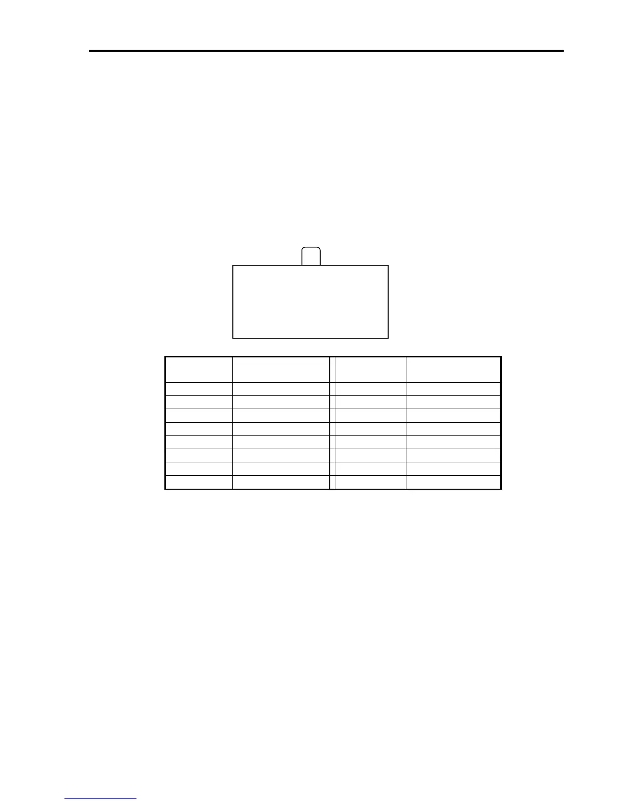
The input lines as seen from the back of the box are arranged as follows (all
connections denoted by “OPT-GND” are optically isolated ground.):
Output
This connector is for up to 8 output lines. These lines are all compatible with
TTL/CMOS level outputs. The Output ports are not setup to drive a 24V external
system unless it accepts TTL/CMOS levels. They are all driven by HCT family
logic. Output logic high is normally 5V and can go down to 3.9V at full load.
Output logic low is normally 0V and can go up to 0.3V at full load. Each of these
signals can provide up to 20mA of current.
Two additional pins on this connector are provided for your output lines: ground and
+5V. These are connected to GND and +5V and are not optically isolated. This 5V
circuit can source up to 100 mA. Any larger current demand would require a larger
power source.
16 15 14 13 12 11 10 9
◦ ◦ ◦ ◦ ◦ ◦ ◦ ◦
◦ ◦ ◦ ◦ ◦ ◦ ◦ ◦
8 7 6 5 4 3 2 1
◦