EasyManua.ls Logo

Flashcut CNC Pro Series - 11 Appendix; Sample Wiring Diagrams; Typical Output Line Circuit

Flashcut CNC Pro Series
59 pages
Print Icon
To Next Page IconTo Next Page
To Previous Page IconTo Previous Page
Loading...
FlashCut CNC Section 11 Appendix
45
11. Appendix
Sample Wiring Diagrams
Typical Output Line Circuit
Signal Generator Model 501A
Solid State Relay
Continental Ind ustries
S50 5-0SJ610-000
+ 3
Load
1
2
AC
Fuse
3.3K
4
OPT
GND
Output1
74ACT16373DL
Q8
U50A
Q1
Q4
Q6
Q7
Q5
Q3
Q2
GPO7
GPO6
GPO5
GPO4
GPO3
GPO2
GPO1
GPO0
22 OHM
11
9
10
13
12
14
R 51P
16
15
Output Line 1
Output Line 8
Output Line 5
Output Line 7
Output Line 6
Output Line 3
Output Line 4
Output Line 2
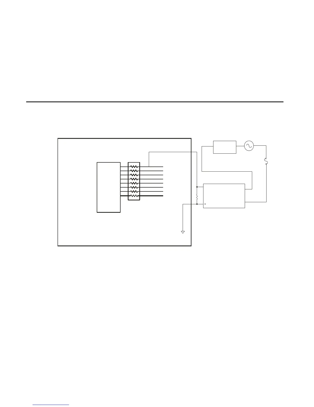
The above schematic shows a typical connection of one solid state relay controlled by output line 1 of the Signal
Generator. A typical load would be a spindle, a vacuum, a laser, etc. In this example, the solid-state relay used is a
Continental Industries model S505-0SJ610-000. It takes a 3 to 32VDC input and has an output of 24-330VAC.
Each of the output signals has a 22-ohm resistor in series with their outputs. This is to reduce any “ringing” at the
transient switching points. Ground and 5V are provided on this connector for your convenience. The FlashCut Spindle
On/Off Relay Box is wired as shown in the above schematic.