FlashCut CNC Section 5 Signal Generator
DB25 PIN22
DB25 PIN23
DB25 PIN24
DB25 PIN25
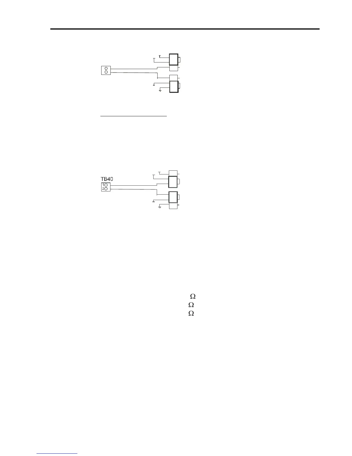
TB40
OPT-GRD
TB-VCC
OPT-VCC
TB-GRD
+5V
1
2
3
JP84
VCC
JP85
GRD
1
2
3
2
1
External Isolated Power
For the best noise immunity, connect an external 5V-24V power supply to the
LED side of the optical couplers. When JP84 shorts pins 2 and 3, OPT VCC
gets its optically isolated power from the TB-VCC. When JP85 shorts pins 2
and 3, OPT GND is directly connected to the TB-GND.
DB25 PIN22
DB25 PIN23
DB25 PIN24
DB25 PIN25
OPT-GRD
TB-VCC
OPT-VCC
TB-GRD
+5V
1
2
3
JP84
VCC
JP85
GRD
3
2
1
Choose only one of the following methods to supply power:
1. Connect a power source to the TB 40 screw terminal.
2. Connect a power source through pins 23 and 25 of the DB-25 connector.
3. Check the resistor value in RP41 to make sure it matches the voltage in
TB40.
TB40 Voltage RP41 Value (10 pin 9 Resistor SIP)
5V 3.9k (Default)
12V 11k
24V 22k
If you are providing an external voltage through pins 23 and 25 of the
DB25 Motor Signal connector or via TB-40, then you must have both JP84
and JP85 jump pins 2 and 3, OTHERWISE SEVERE DAMAGE COULD
OCCUR.
JP 86 – USB to Chassis Ground
This jumper connects the USB shield to the chassis ground of the Signal Generator
when jumped.