FlashCut CNC Section 9 Power Board
9. Power Board
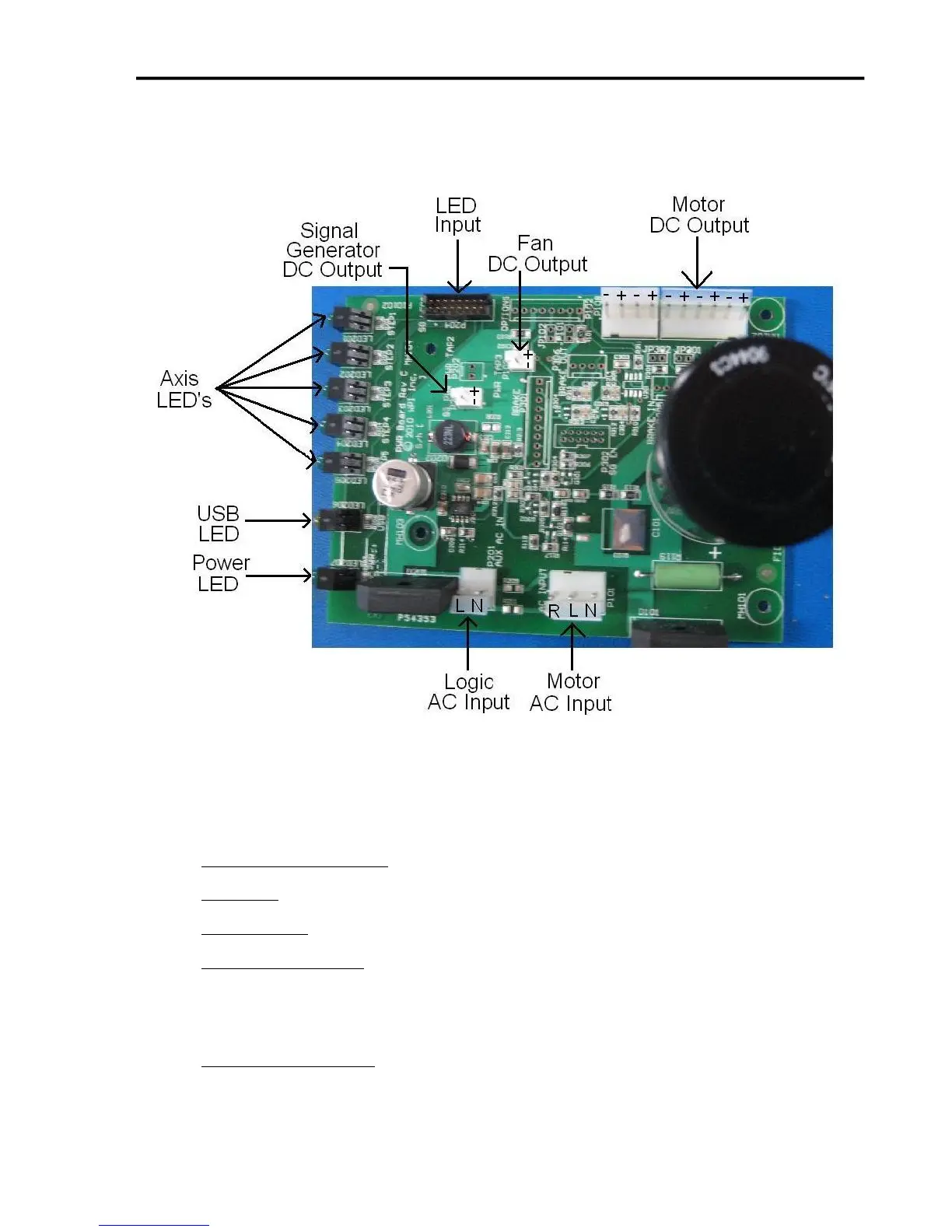
The function of the Power Board is to supply DC voltage to the drive modules as well
as to the cooling fan and logic signals to the Signal Generator. The power enters the
board in the form AC voltage from a transformer; the AC voltage is then converted to DC
voltage. The Power Board also contains the indication LED’s:
AXIS LED’s 1, 2, 3, 4, 5 – Turns green when the respective axis is moving.
USB LED– Turns yellow when connected to the host PC USB port.
POWER LED– Turns green when the power switch is turned on.
LOGIC AC INPUT- This connector takes in the power from the transformer for the logic
signals. The AC voltage from the transformer is then converted to a DC voltage to be
used for logic signals. The two contacts are labeled as follows: L is the hot, N is the
neutral.
MOTOR AC INPUT- This connector takes in the power from the transformer for the
drive modules. The AC voltage from the transformer is then converted to a DC voltage
of 40-80V, depending on the connection configuration, to be used for powering the drive