FlashCut CNC Section 6 Drive Settings
L
oa
d
Inertia
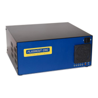
The drives include anti-resonance and electronic damping features which
greatly improve motor performance. To perform optimally, the drive must
understand the electromechanical characteristics of the motor and load. Most
of this is done automatically when you select the motor by setting the rotary
switch. To further enhance performance you must set a switch to indicate the
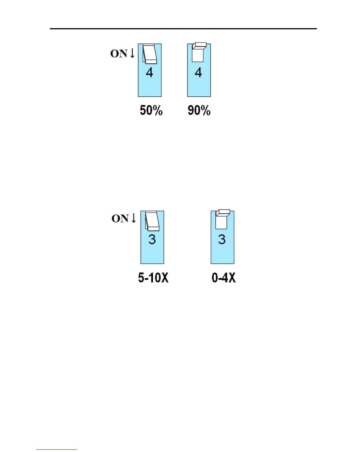
appropriate inertia ratio of the load and motor. The ranges are 0 to 4X and 5
to 10X. Simply divide the load inertia by the rotor inertia to determine the
ratio, then set switch 3 accordingly, as shown.
Step Size
The drive module requires a source of step pulses to command motion. This
may be a PLC, an indexer, a motion controller or another type of device. The
only requirement is that the device be able to produce step pulses whose
frequency is in proportion to the desired motor speed, and be able to
smoothly ramp the step speed up and down to produce smooth motor
acceleration and deceleration.
Smaller step sizes result in smoother motion and more precise speed, but also
require a higher step pulse frequency to achieve maximum speed. The
smallest step size of the drives is 1/20,000
th
of a motor turn while the
maximum step rate of the signal generator is typically between 50,000 and