FlashCut CNC Section 5 Signal Generator
BE VERY CAREFUL WHEN DOING ANY WIRING. IMPROPER WIRING
WILL DAMAGE THE SIGNAL GENERATOR.
The output lines are all initialized to low (0V) when you turn on the Signal
Generator. Output lines 1 and 2 are also connected through pins 1 and 2 respectively
of the Motor Signal connector. This makes it convenient to connect up to 2 output
signals to an external motor driver box to drive devices such as solid-state relays that
might be in an external motor driver box.
The receptacle that plugs into this connector is a Molex-Waldom Mini-Fit Jr. Series
10 pin receptacle (part number 39-01-2100), with female pins (part number 39-00-
0039 or 39-00-0047 for 22 gauge or thinner wires).
The Molex 63811-1000 for 14-24 AWG universal or Molex 11-01-0197 Crimp
Tools are recommended for installing the pins. Kits containing connectors and pins
are available through FlashCut CNC or an electronics distributor.
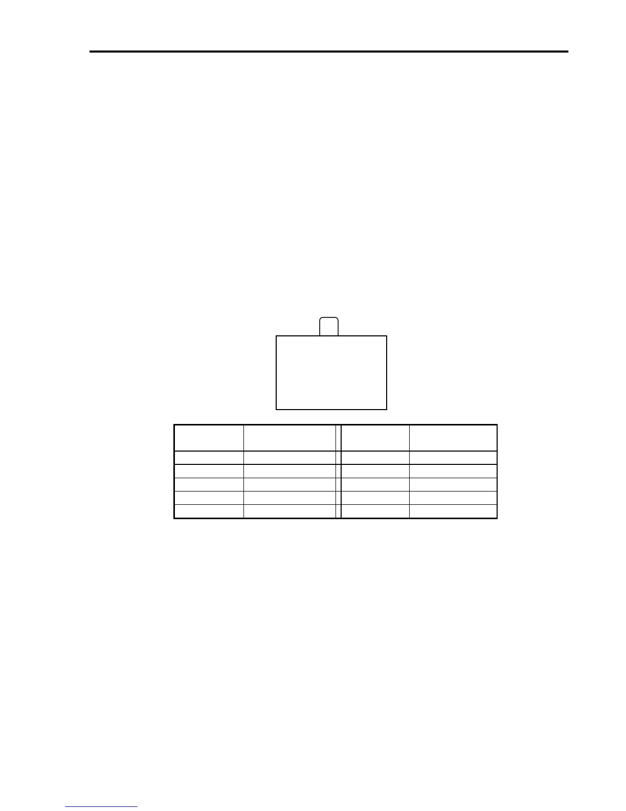
The output lines as seen from the back of the box are arranged as follows:
Jumper Settings
Pin 1 of all jumpers is indicated by a small white dot printed on the PCB.
10 9 8 7 6
◦ ◦ ◦ ◦ ◦
◦ ◦ ◦ ◦ ◦
5 4 3 2 1
◦