FlashCut CNC Section 9 Power Board
modules. The three contacts are labeled as follows: R is the reserve, L is the hot, N is the
neutral. The reserve and the hot may be switched to vary the voltage. For example if R is
red and L is purple the resulting DC voltage is approximately 67 VDC, where if R is
purple and L is red the resulting DC voltage is approximately 80 VDC.
SIGNAL GENERATOR DC OUTPUT- This output sends a 9 VDC signal to power the
Signal Generator. When viewing the power board in the configuration above the top
contact of the signal generator DC output is positive and the bottom contact is negative.
FAN DC OUTPUT- This output sends a 24 VDC signal to power the fan for cooling the
box. When viewing the power board in the configuration above the top contact of the fan
DC output is positive and the bottom contact is negative.
MOTOR DC OUTPUT- This output sends a 40-80 VDC, depending on the connection
configuration, DC signal to power the drive modules. Power for up to 5 individually
powered drive modules. The contacts alternate positive and negative starting with
positive on the contact nearest the large capacitor.
LED INPUT- This input receives logic signal from the signal generator in order to
illuminate any of the 7 LED’s indicating axis movement, power or USB connectivity.
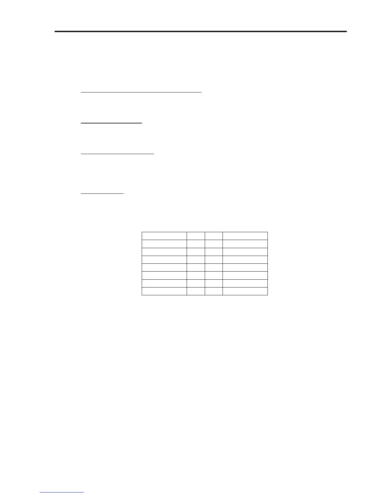
The contact connections for the LED input are as follows:
JP31 – STATUS LEDS
2 X 8 - 2MM SPACING