EasyManua.ls Logo

Flashcut CNC Pro Series - Page 25

Flashcut CNC Pro Series
59 pages
Print Icon
To Next Page IconTo Next Page
To Previous Page IconTo Previous Page
Loading...
FlashCut CNC Section 5 Signal Generator
25
The Axis plug-in interfaces are used to add additional functions to the main signal
generator board. For example, a stepper drive plug-in card or cable will enable
you to drive a stepper motor directly from the signal generator box.
1 2
3 4
5 6
7 8
9 10
11 12
13 14
15 16
17 18
19 20
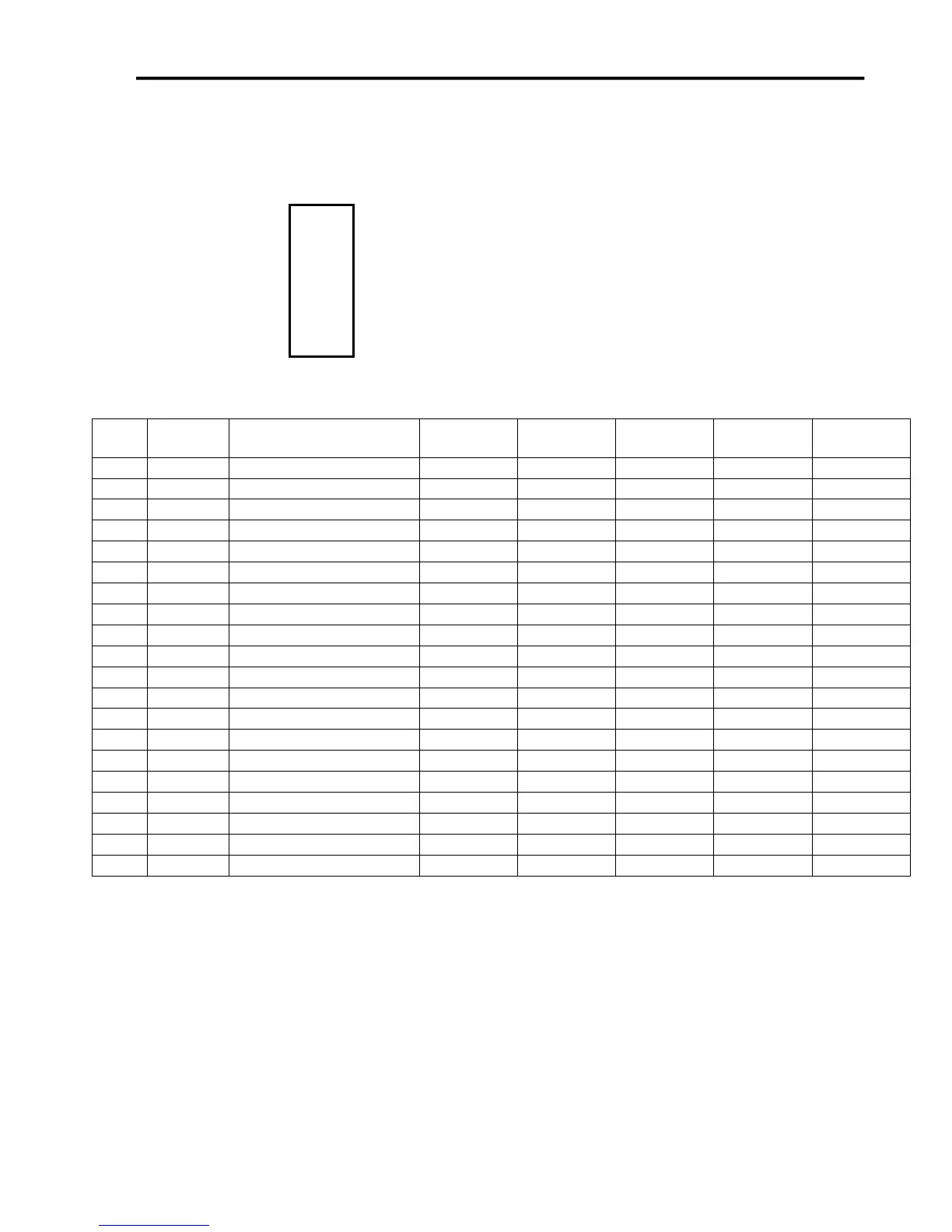
Each of these plug-in cards is a SKT10X2 connector, with the
pin configuration on the left. Pin numbers 1-5, 7, 13, 15 and
17-20 perform the same function on each jumper.
Per the chart below, pins 6, 8-12, 14 and 16 have different
values of Status, Fault, InputA, Dir, InputB, Step, SCOM and
CS respectively for each plug-in card.
Pin
No.
Label
Function
JP-71
JP-72
JP-73
JP-74
JP-75
1
HV-PWR
High Voltage Power
HV-PWR
HV-PWR
HV-PWR
HV-PWR
HV-PWR
2
HV-PWR
High Voltage Power
HV-PWR
HV-PWR
HV-PWR
HV-PWR
HV-PWR
3
GND
Ground
GND
GND
GND
GND
GND
4
GND
Ground
GND
GND
GND
GND
GND
5
RxD2
Serial Com. Receive
RxD2
RxD2
RxD2
RxD2
RxD2
6
STATUS
Status
STATUS1
STATUS2
STATUS3
STATUS4
STATUS5
7
TxD2
Serial Com. Transmit
TxD2
TxD2
TxD2
TxD2
TxD2
8
FAULT
Fault Indicator
FAULT1
FAULT2
FAULT3
FAULT4
FAULT5
9
INPUTA
Input A
IN8
IN10
IN12
IN14
IN16
10
DR
Direction
DR1
DR2
DR3
DR4
DR5
11
INPUTB
Input B
IN9
IN11
IN13
IN15
IN17
12
ST
Step
ST1
ST2
ST3
ST4
ST5
13
SM0
SM0
SM0
SM0
SM0
SM0
SM0
14
SCOM
SCOM
SCOM1
SCOM2
SCOM3
SCOM4
SCOM5
15
SM1
SM1
SM1
SM1
SM1
SM1
SM1
16
CS
Chip Select
CS1
CS2
CS3
CS4
CS5
17
ENA
Enable
ENA
ENA
ENA
ENA
ENA
18
+5V
+5V
+5V
+5V
+5V
+5V
+5V
19
GND
GND
GND
GND
GND
GND
GND
20
GND
Ground
GND
GND
GND
GND
GND