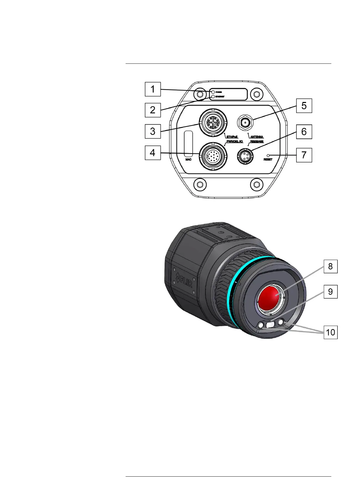
Camera parts
7
Figure 7.1 View from the rear
Figure 7.2 View from the front
1. Power/error indicator LED (blue/red).
2. Ethernet communication indicator LED (green).
3. Ethernet/PoE connector, X-coded.
4. Power-I/O connector, A-coded.
5. Antenna.
6. RS232/485 connector, A-coded.
7. Factory reset button.
8. Infrared sensor.
9. Visual camera.
10. LED lamps.
For details, see section 17 Indicator LEDs and factory reset button, page 55.
#T810409; r. AB/66574/66574; en-US
14
 Loading...