PTU-5 User Manual
Copyright 2017, FLIR Commercial Systems, Inc.
10
3.2 - Installation Components
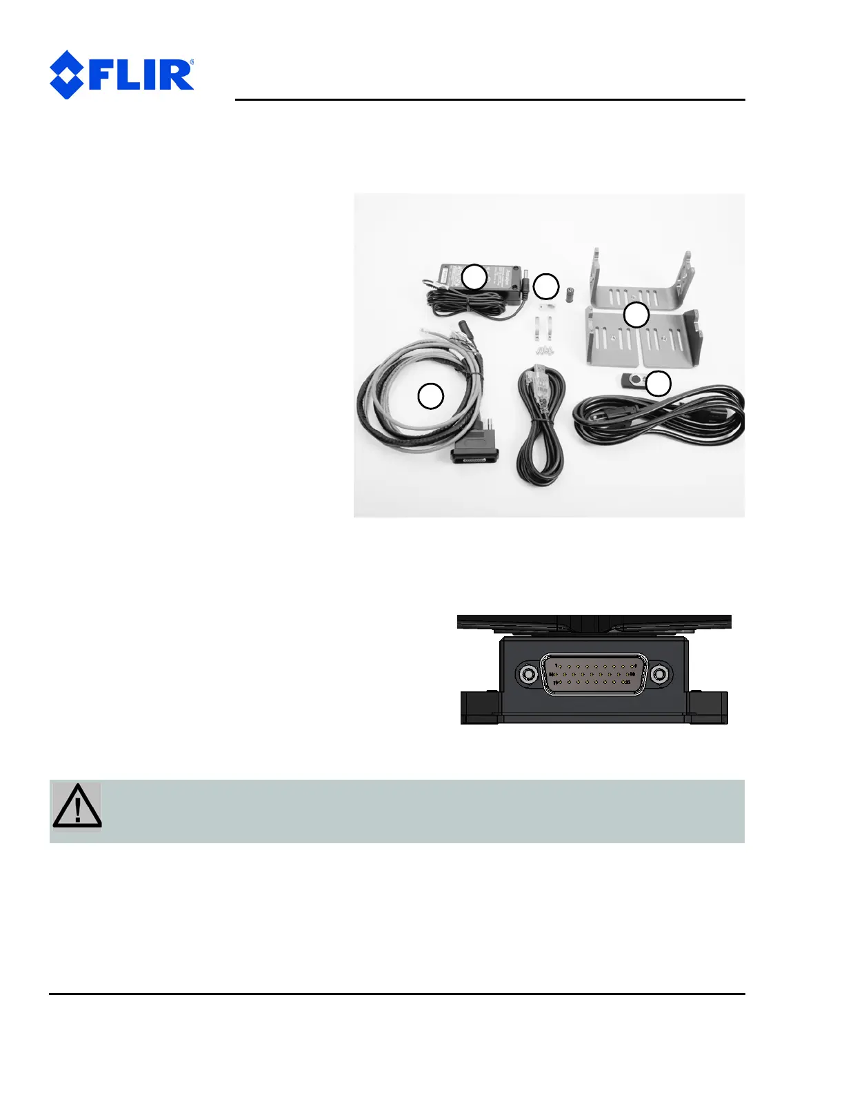
A complete PTU-5 system configuration requires the following components:
• PTU-5 (not shown)
• AC/DC power supply (PT-PS-INT-30V) –
Optional – (1)
• Breakout cable (308-0278-XX-00) –
Optional – (2)
• USB to RS-485 converter (PTU-CONV-
USB-RS485) – Optional – (3)
• Side payload mounting brackets (261-
2664-00)– Optional – (4)
• PTU-5 User’s Manual (this document; 5)
• Pan-Tilt E Series Command Reference
Manual (5)
3.3 - Basic Setup
To perform a basic PTU setup and
installation:
1. Mount the PTU securely to a lab bench, tripod, or other
stable platform. Verify that there is enough clearance
around the unit. See “Mounting the Unit” on page 15
for detailed mounting instructions.
2. Attach either the optional breakout cable or customer-
supplied cable to the 26-pin connector at the base of
the PTU by inserting the cable into the connector and
then tightening the mounting screws (one each on the
left and right sides of the connector).
CAUTION: DISCONNECTING THE CABLE WHILE THE PTU IS POWERED ON CAN
DAMAGE THE UNIT. ALWAYS POWER DOWN THE PTU BEFORE DISCONNECTING THE
CABLE.


 To Next Page