Copyright 2017, FLIR Commercial Systems, Inc.
15
4 - Installation & Setup
This section describes proper mechanical and electrical PTU-5 installation.
4.1 - Mounting the Unit
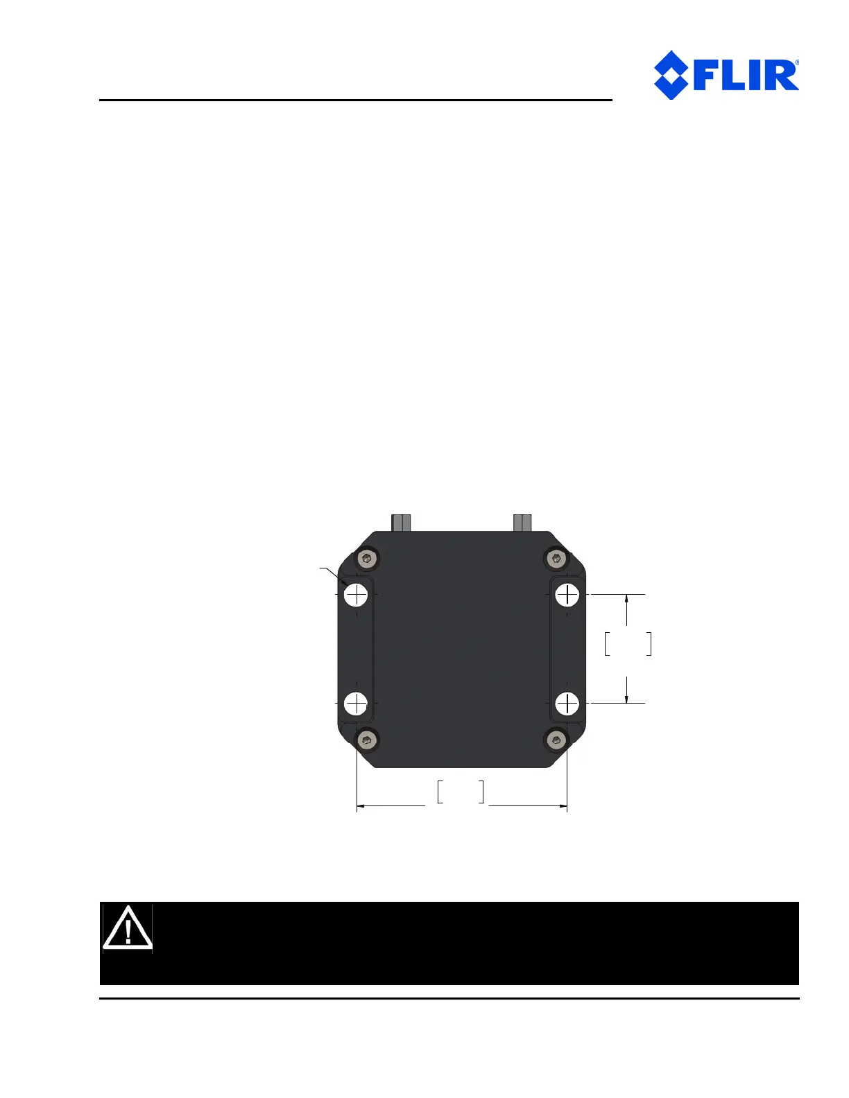
The basic mounting pattern uses four #1/4-20 screws in a 1.18” (30mm) by 2.28” (58mm) rectangular
pattern. All four mounting screws must be used, and mount must be strong enough to support the
combined load of the PTU, payload, and additional forces exerted on the system (such as wind, G forces,
etc.). A good rule of thumb is that the mount must be capable of supporting at least four times the
combined weight of the PTU and payload. For example, a mount for a PTU-5 must be able to support at
least 48lbs.
Figure 4-1: Hole Mounting Patterns
WARNING: FAILURE TO USE ALL FOUR MOUNTING SCREWS AND/OR TO SECURE THE
PTU AND ITS PAYLOAD TO A SUFFICIENTLY STRONG MOUNTING CAN CAUSE THE
INSTALLATION TO FAIL. THIS CAN RESULT IN PERSONAL INJURY OR DEATH, AND/OR
DAMAGE TO THE PTU AND/OR PAYLOAD.
2.28
58.0
4X 1/4 - 20
TAPPED HOLE
 Loading...