Automatic operation
Switching the electric motor in the unit
on generates a rotary motion. This is
transmitted to the reduction gear by a
timing belt. This causes the valve stem
in the unit to turn (see “Uses and func-
tion”).
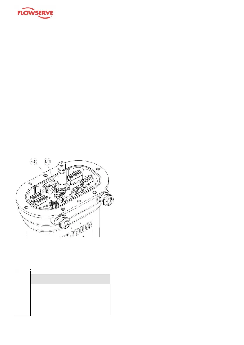
In automatic operation, the end posi-
tions of the unit are recorded by end-
position limit switches (4.2).
These limit switch signals must then be
integrated in the control system (area
of responsibility of the plant designer)
to switch on/off the motor and brake
(see electrical wiring diagram page 23).
The end-position limit switches are
inside the unit.
The required end positions are individ-
ually adjustable via the switching cams
(4.11).
ATTENTION!
Setting the switching cams,
even after repairs, shall only be
carried out by authorised per-
sonnel.