The shaft gap, or distance between shaft ends
(DBSE), must be in accordance with the certified
General Arrangement Drawing and must be
measured with pump and driver shafts in the center
of their axial end float. Motor with sleeve bearings is
to be aligned with rotor at magnetic center.
Move driver to insure proper gap distance.
It is recommended that the pump hold-
down bolting be torqued before taking any alignment
measurements. This makes the pump the fixed
machine and the driver the movable machine. In
certain cases, however, it may be impractical to move
the driver; therefore, the pump may have to be
Bracket sag must be determined and included in the
and read indicator and register.
the sag is equal on both sides.
Before moving the equipment vertically, it is important
that the vertical thermal expansion be taken into
and/or driver instructions for
recommended cold vertical setting (if thermal
The shims between the motor feet and mounting
surface should be clean and dry. This is especially
critical for equipment that has been in service for
some time and need to be realigned. Water, dirt and
rust may change the height of the shim pack over a
period of time. Shims should be made large enough
to support the weight of the motor on its mounting
foot. Do not use many thin shims, as this may result
Move the equipment vertically by adding or removing
the calculated thickness of shims. Torque equipment
hold-down bolting to required values.
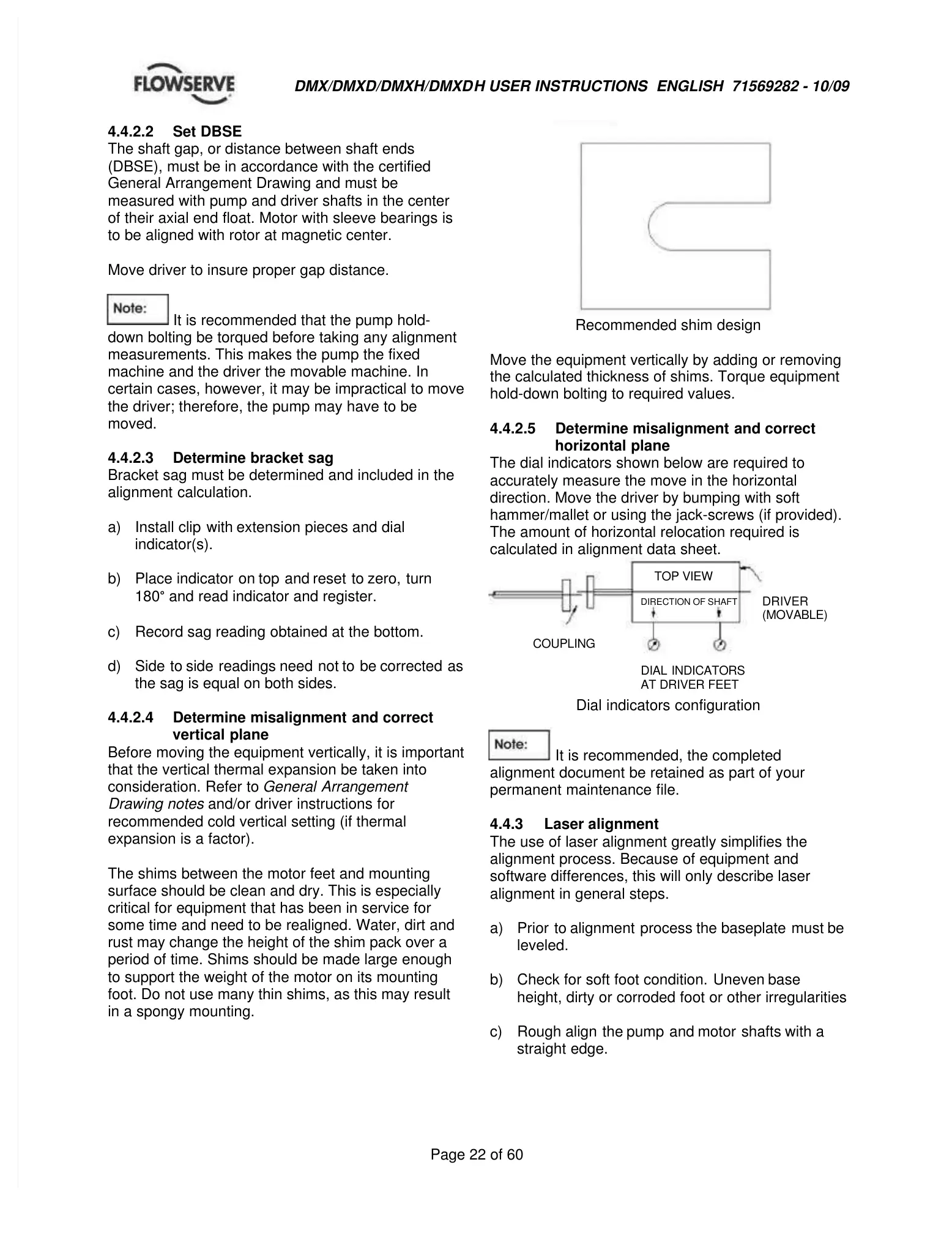
The dial indicators shown below are required to
accurately measure the move in the horizontal
direction. Move the driver by bumping with soft
hammer/mallet or using the jack-screws (if provided).
The amount of horizontal relocation required is
calculated in alignment data sheet.
Dial indicators configuration
It is recommended, the completed
alignment document be retained as part of your
permanent maintenance file.
The use of laser alignment greatly simplifies the
alignment process. Because of equipment and
software differences, this will only describe laser
alignment in general steps.
height, dirty or corroded foot or other irregularities