the laser target on the motor shaft.
and angular alignment per laser unit’s output.
Make the necessary corrections by adding or by
removing shims at the motor feet.
and angular alignment per the laser unit’s output
by using a soft mallet or adjusting screws.
The angular and offset coupling alignment must be
0.0254 mm (0.001 in.) TIR.
0.0762 mm (0.003 in.) TIR.
consult turbine manufacturer.)
instructions included in Section 8 of this manual.
Pump hold down bolts are to be torqued to the
proper value and dowel pins put in two diagonally
to expand with temperature away from coupling end
of pump. The units that come under this classification
must have the pump support feet dowelled to the
pedestal at the coupling end. This maintains the
coupling gap at the desired amount.
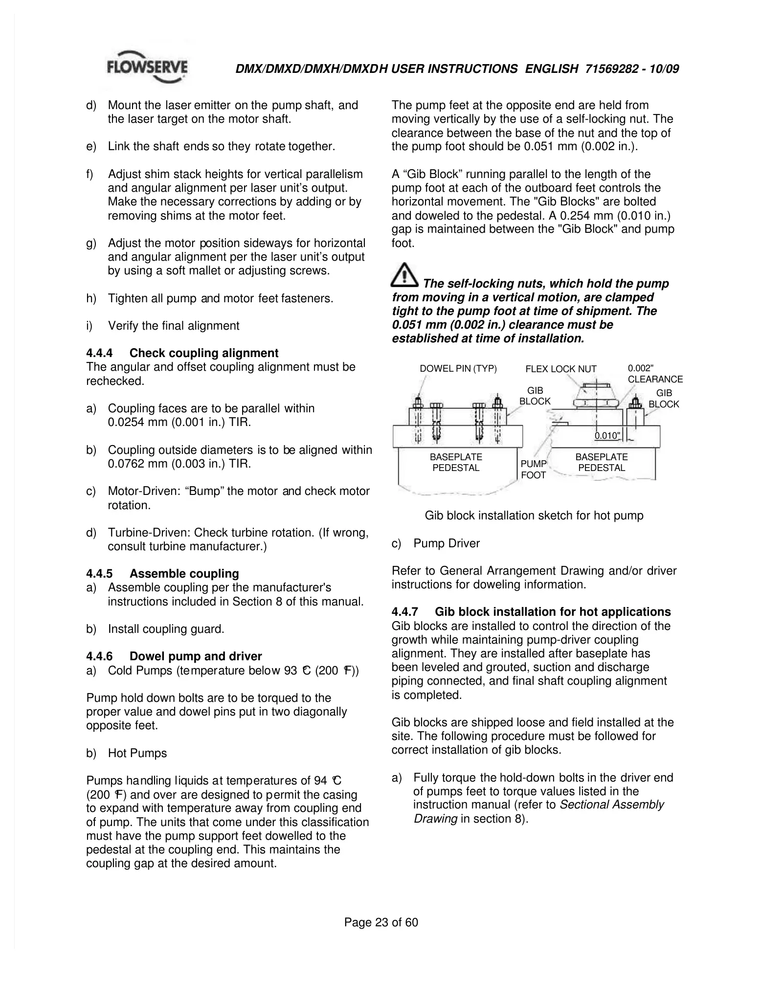
The pump feet at the opposite end are held from
moving vertically by the use of a self-locking nut. The
clearance between the base of the nut and the top of
the pump foot should be 0.051 mm (0.002 in.).
A “Gib Block” running parallel to the length of the
pump foot at each of the outboard feet controls the
horizontal movement. The "Gib Blocks" are bolted
and doweled to the pedestal. A 0.254 mm (0.010 in.)
gap is maintained between the "Gib Block" and pump
The self-locking nuts, which hold the pump
from moving in a vertical motion, are clamped
tight to the pump foot at time of shipment. The
0.051 mm (0.002 in.) clearance must be
established at time of installation.
Gib block installation sketch for hot pump
Refer to General Arrangement Drawing and/or driver
instructions for doweling information.
Gib blocks are installed to control the direction of the
growth while maintaining pump-driver coupling
alignment. They are installed after baseplate has
been leveled and grouted, suction and discharge
piping connected, and final shaft coupling alignment
Gib blocks are shipped loose and field installed at the
site. The following procedure must be followed for
correct installation of gib blocks.
of pumps feet to torque values listed in the
instruction manual (refer to