13
Limitorque
®
L120-190 through L120-2000 FCD LMENIM1203-01-A4 – 05/15
flowserve.com
4.3.1 Mounting Base
The mounting hole sizes and quantities are as detailed in Table 4.1, below:
Table 4.1 – Mounting Base Dimensions
Actuator Size
Mounting Holes Tap Size
ISO
Bolt Circle
ISO
Quantity MSS MSS
L120-190 8 ¾–10 x 1.13 M20 x 2.5 x 32 11.75 298 mm
L120-420 8
7
⁄8–9 x 1.75 N/A 14.0 N/A
L120-800 (Torque Only) 8 ¾–10 x 1.63 N/A 17.0 N/A
L120-800 (Thrust Only) 8 1.25–7 x 2.0 N/A 16 N/A
L120-2000 (Torque Only)
16
1–8 x 2.0 N/A 23.5 N/A
L120-2000 (Thrust Only) 12 1-½–6 x 3.0 N/A 18.0 N/A
4.3.2 Stem Acceptance
The maximum stem acceptance is provided in Table 4.2, below:
Table 4.2 – Maximum Stem Acceptance
Actuator size
Drive 2 Tapped Drive 1 Bore Drive 1 Key
inch mm inch mm inch mm
L120-190 3.5 89 2.875 73 ¾ x ¼ 20 x 12
L120-420 5 127 4.25 108 1 x ¾ 28 x 16
L120-800 5 127 7 178 1 x ¾ 32 x 18
L120-2000 6.25 159 8.00 203 1¼ x
7
⁄8 40 x 22
NOTE: For complete mounting dimensions, see sales brochure LMENBR1200.
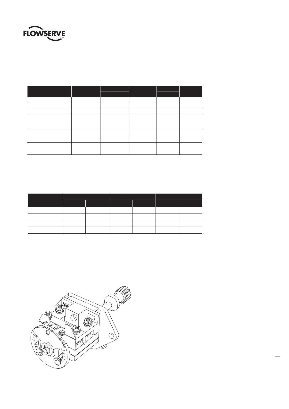
4.4 Double Torque Switch
The torque switch is designed to protect the actuator in open and close directions.
Figure 4.1 – Double Torque Switch
NOTE: See Caution and Note on following page.