Limitorque
®
L120-190 through L120-2000 FCD LMENIM1203-01-A4 – 05/15
18
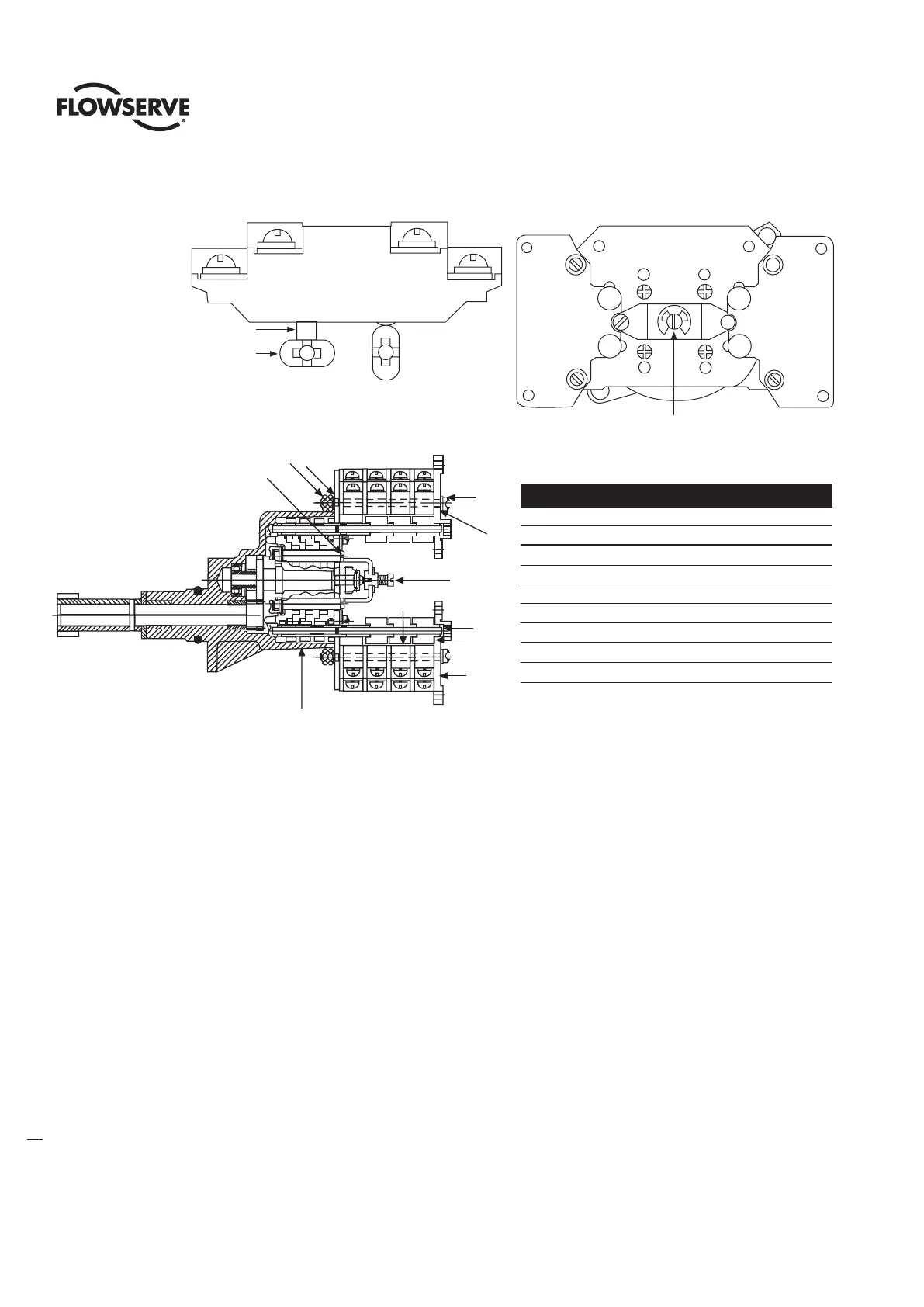
Figure 4.5 – Setting Geared Limit Switch
Unless otherwise noted part numbers refer to Figure 4.5.
1. Open the Limit Switch Compartment Cover (piece #200-1 of Figure 7.3 for L120-190 and -420,
Figure 7.6 for L120-800, and Figure 7.7 for L120-2000).
2. Put the actuator into manual operation. Use the handwheel to operate the valve in the “open”
direction. While operating the valve, note the direction of rotation of the Intermediate Shaft
corresponding to the rotor or rotors to be set.
3. When the valve is fully open, close it one turn of the handwheel to allow for coast of moving parts.
4. Push in the Clutch Screw and turn one-quarter turn. The rod will latch in this depressed position.
5. Refer to the applicable wiring diagram for contact development. The limit switch contact is closed
when the rotor is engaged with the plunger. If the rotor to be set has not turned 90° to operate
the plunger, turn the intermediate shaft in the same direction as noted in Step No. 2 until the rotor
clearly trips the switches. This rotor is now set correctly.
6. If the intermediate position rotors 1 and 2 are also to be set at any desired position, repeat the
setting operation in steps 1 through 5 above.
7. Before moving the valve, depress and turn the Clutch Screw counterclockwise one-quarter turn to
the spring-released position. Insert a screwdriver into the intermediate shafts to ensure that they are
loaded in position and will not rotate.
Contact Open
Contact Close
Contact Plunger
Rotor Cam
Clutch Screw
Open
Close
A
B
C
D
INT - 1 INT - 2
Piece Quantity Description
11 Gear Frame Assembly
22 8-Switch Contact Block
312 Rotor Segment (short)
44 Rotor Shaft
54 Machine Screw
64 Flat Washer
74 Lock Washer
88 Hex Nut
94 Rotor Segments (long)
1
6
5
7
8
Clutch
Screw
4
9
3
2
Intermediate Shaft