15
Limitorque
®
L120-190 through L120-2000 FCD LMENIM1203-01-A4 – 05/15
flowserve.com
4.4.2 Balancing Torque Switch
Item letters correspond to Figure 4.2.
1. Place the actuator in manual mode.
2. Remove the load from the wormshaft spring pack.
NOTE: If the actuator torque switch has opened and de-energized the actuator, release the torque
buildup by operating the actuator manually in opposite direction ½ to 1 turn.
3. Note the open and close torque switch settings prior to re-installing the torque switch.
4. Loosen Screws (A) and position both Pointers (B) at the #1 setting; tighten Screws (A).
5. Mount the torque switch and tighten the mounting screws. Verify that both contact pointers are
touching the arms. The interface between the pointers and the arm is found beneath the torque
switch dial. If the pointers and the arms are not in contact, the clearance on the open and close
torque switches should be equal. If not equal, the torque switch needs to be balanced. (See Step 7.)
6. If the pointers and arms are in contact on both sides of the switch, manually rotate the torque
switch dial clockwise and counter-clockwise to determine if there is equal backlash in both direc-
tions of rotation. If there is not equal backlash in both directions, the torque switch needs to be
balanced. (See Step 7.)
7. Loosen both hex nuts.
8. Back out one setscrew and tighten the other setscrew until there is equal backlash in both directions
of rotation of the dial, or equal clearance between the pointers and arms.
9. Tighten the hex nuts and return the torque switch to its original settings.
a CAUTION: The balancing screws should not be touched except during the balancing procedure.
The switch is now balanced and ready for the pointers to be returned to their original settings.
4.4.3 Torque Switch Terminal Connections
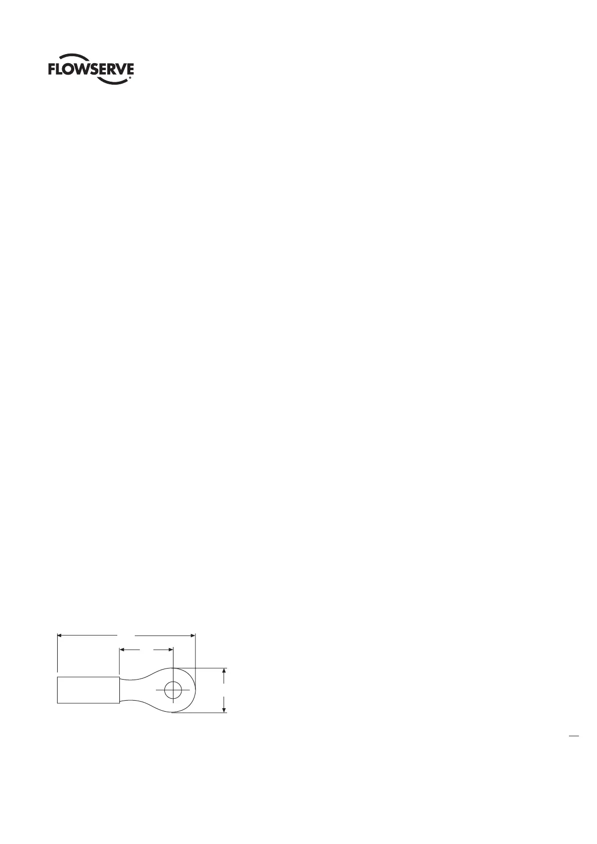
Wiring connections to the L120 geared limit switch, torque switch, and marathon terminal strips are to
be made using ring-tongue terminals as shown below:
Figure 4.3 – Ring Tongue Terminal
See Table 4.3, next page
C
B