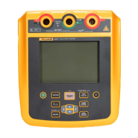
Insulation Tester
The Tester
11
Guard Terminal Use
Note
Insulation resistance is measured between the Earth terminal (E) and
Live terminal (L) output connections. The Guard terminal (G) is at the
same potential as the E terminal but is not in the measurement path.
For most tests, use only two test leads. Connect the E and L test leads to the
corresponding inputs on the Tester. Connect the test lead probes to the
circuit under test. The Guard (G) terminal is left unconnected.
For the best accuracy when you measure very high resistances, use three-wire
measurements including G. G is at the same potential as E, and can be used to
prevent surface leakage or other unwanted leakage currents from degrading
the accuracy of the insulation resistance measurement.
G
Continuity (1537 only)
H
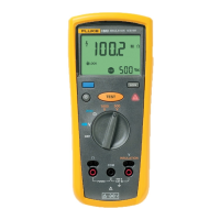
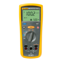
Test Voltage Setting
I
Te s t Volta g e
J
Discharging
K
Possible hazardous voltage is at the test terminals
L
Battery Status
M
Delete/Delete All
N
Save
O
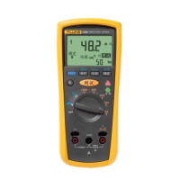
Bar graph display of insulation resistance
P
V ac or V dc voltage indicator
Q
Insulation and DMM resistance measurement indicator
R
Text display; shows voltage, test current, capacitance, programmable
test voltages, and menu options
S
Memory Status
T
Pass/Fail
Table 4. Display Features (cont.)