1550B
Users Manual
6
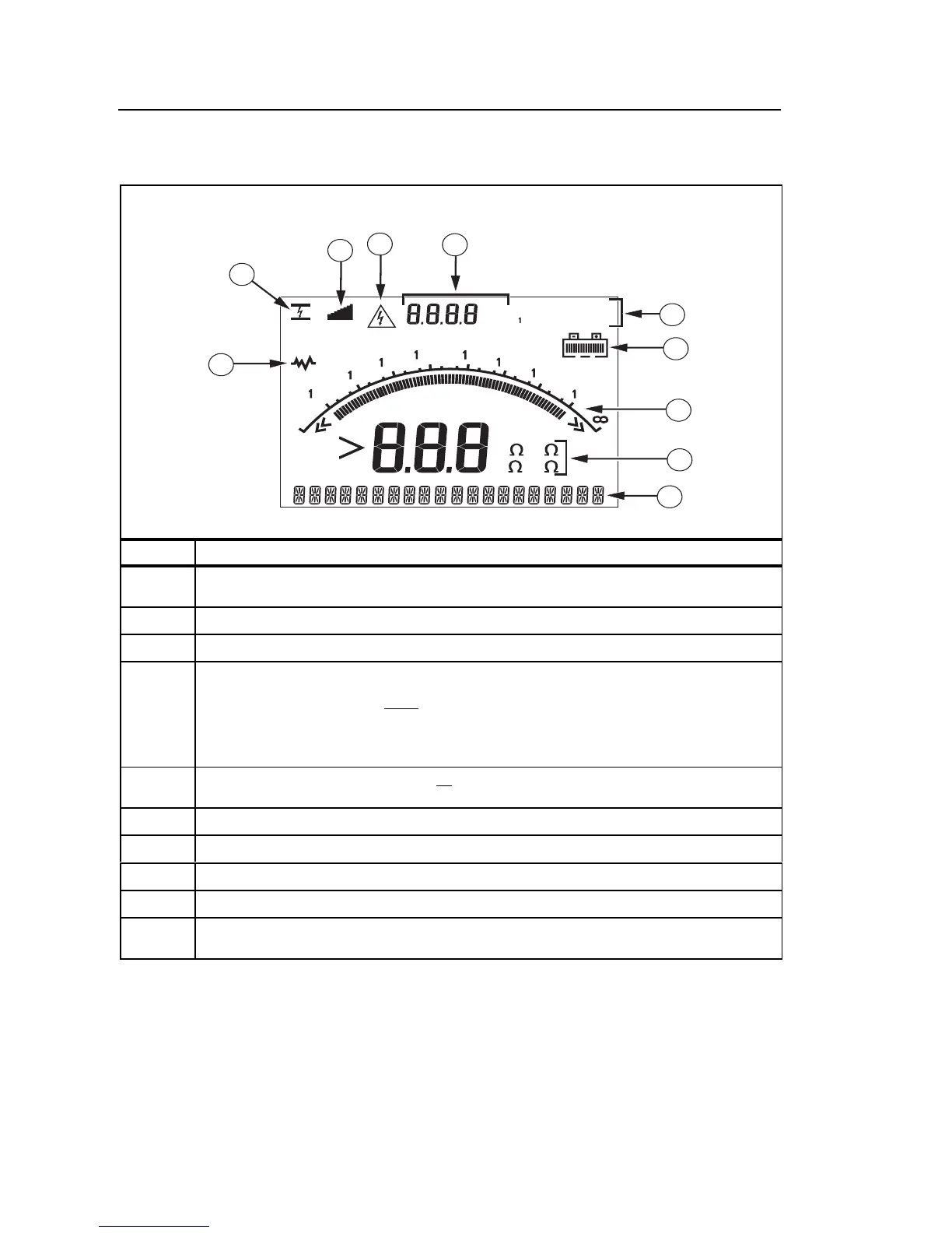
Understanding the Display
Display annunciators are shown and described in Figure 3.
00k
0
0M
G
V
0G
T
00G
GT
Mk
00M
M
000V 500V
5000V 2500V
1
2
8
10
9
3
4
5
7
6
250V
ASW03F.EPS
Item Description
1
Interference present. Displayed readings may be outside the specified
accuracy range.
2
Electrical breakdown in Ramp mode.
3
Ramp mode indicator.
4
Potentially hazardous voltage is present at the test terminals.
XW Warning: Before and after testing, confirm that the Meter does not
indicate the presence of a hazardous voltage. If the Meter beeps
continuously and a hazardous voltage is present, disconnect test leads
and remove power from the circuit under test.
5
Voltage sourced by the Meter or from the circuit under test that is present
at terminals of the Meter.
6
Test voltage selection (250 V, 500 V, 1000 V, 2500 V, or 5000 V)
7
Battery charge status.
8
Bar graph display of insulation resistance.
9
Digital display of insulation resistance.
t
Text display. Indicates voltage, test current, capacitance, programmable
test voltages, and menu options.
Figure 3. Display Features
Charging the Battery
XW Warning
To avoid possible electric shock or personal injury, disconnect the test
leads from the Meter before charging the battery.