1550B
Users Manual
8
Using the Guard Terminal
Note
Insulation resistance is measured between the
+
and
−
output
connections. The Guard terminal (G) is at the same potential as the
negative (
−
) terminal but is not in the measurement path.
For most tests, only two test leads are used, connecting the positive (+) and
negative (−) terminals on the Meter to the circuit under test. The Guard (G)
terminal is left unconnected.
When measuring very high resistances, you can obtain more accurate readings
by making a three-wire measurement using the Guard terminal. The Guard
terminal is at the same potential as the negative (−) terminal, and can be used
to prevent surface leakage or other unwanted leakage currents from degrading
the accuracy of the insulation resistance measurement.
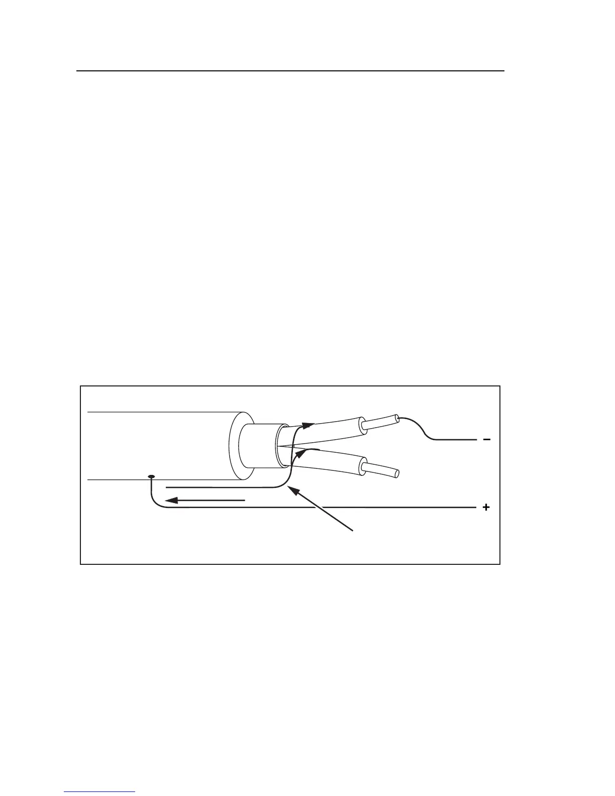
Figure 5 shows how to measure the resistance from one of the conductors to
the outer shield. In this case, there is a leakage current along the surface of the
inner insulation near the end of the cable. This leakage adds to the current that
the negative terminal detects, and will cause the Meter to read a lower
resistance than it should.
Surface Leakage
Current
Shield
( )
( )
ASW13F.EPS
Figure 5. Surface Leakage Current